Light Triggered Fan Timer
Intro:
A small weekend project, using my favorite ESP8266 (WeMos D1 Mini) controller – A Light Triggered Fan Timer – to keep the air in the smallest room fresh – but also suitable for a bathroom to remove moist air from the shower.
Of course you can buy a ready-made fan, which connects to your light, and will run for half an hour when you turn the light on. But… that’s just too easy / no fun, and when building this yourself, you can add some features!
Features:
- When you turn ON the LIGHT, the FAN turns OFF (if running), to allow for some quiet time (it’s a noisy fan). However, after 5 minutes, the FAN will turn ON for half an hour (just in case someone forgot to turn off the light).
- When you turn OFF the LIGHT, the FAN turns ON for half an hour.
- If you quickly toggle the light (from off) to ON – OFF – ON, the FAN will turn ON for half an hour.
- If you quickly toggle the light (from on) to OFF – ON – OFF, the FAN will turn OFF, and stay off.
Note: where I write “quickly”, you actually get a full 2 seconds to do the last two switch clicks, which is quite long.
Used components:
- WeMos D1 Mini (ESP8266 WiFi micro controller module)
- DC-DC Converter (input range 4.5V to 24V, output 5V, max current 3A, average current 2.1A – and my guess is we only need about 200 to 300 mA)
- WeMos D1 Mini Relay Shield
- TSL2561 Light Sensor
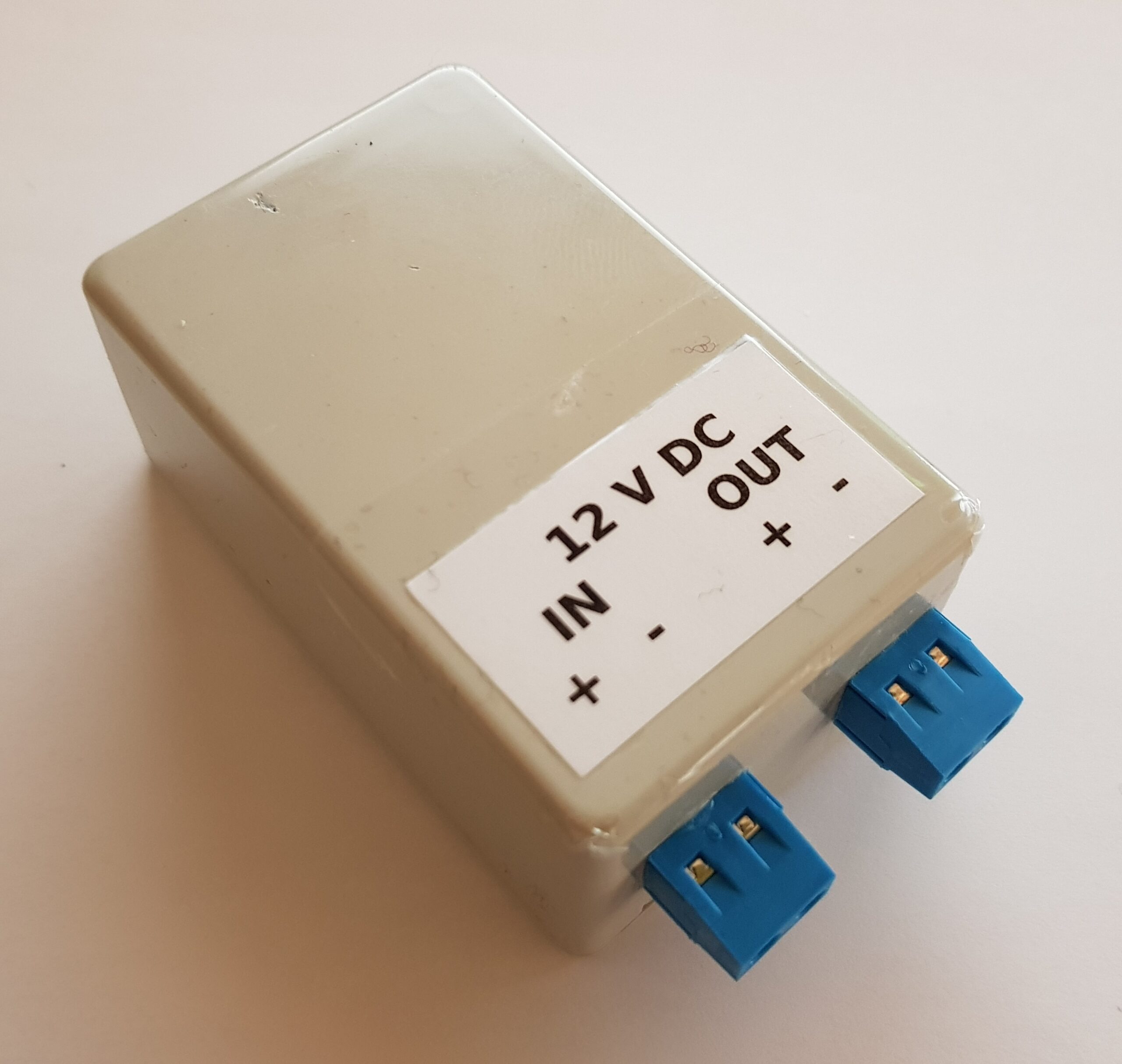
- 12V DC Power Brick
- 12V Computer Fan (just an old one, installed inside the existing air-vent channel)
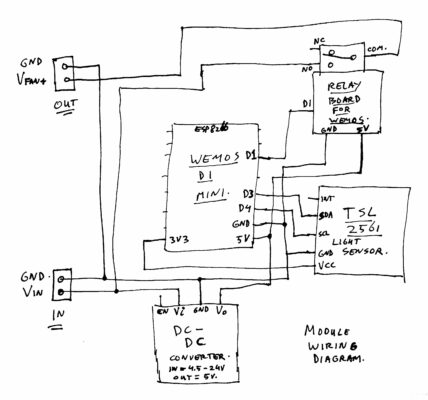
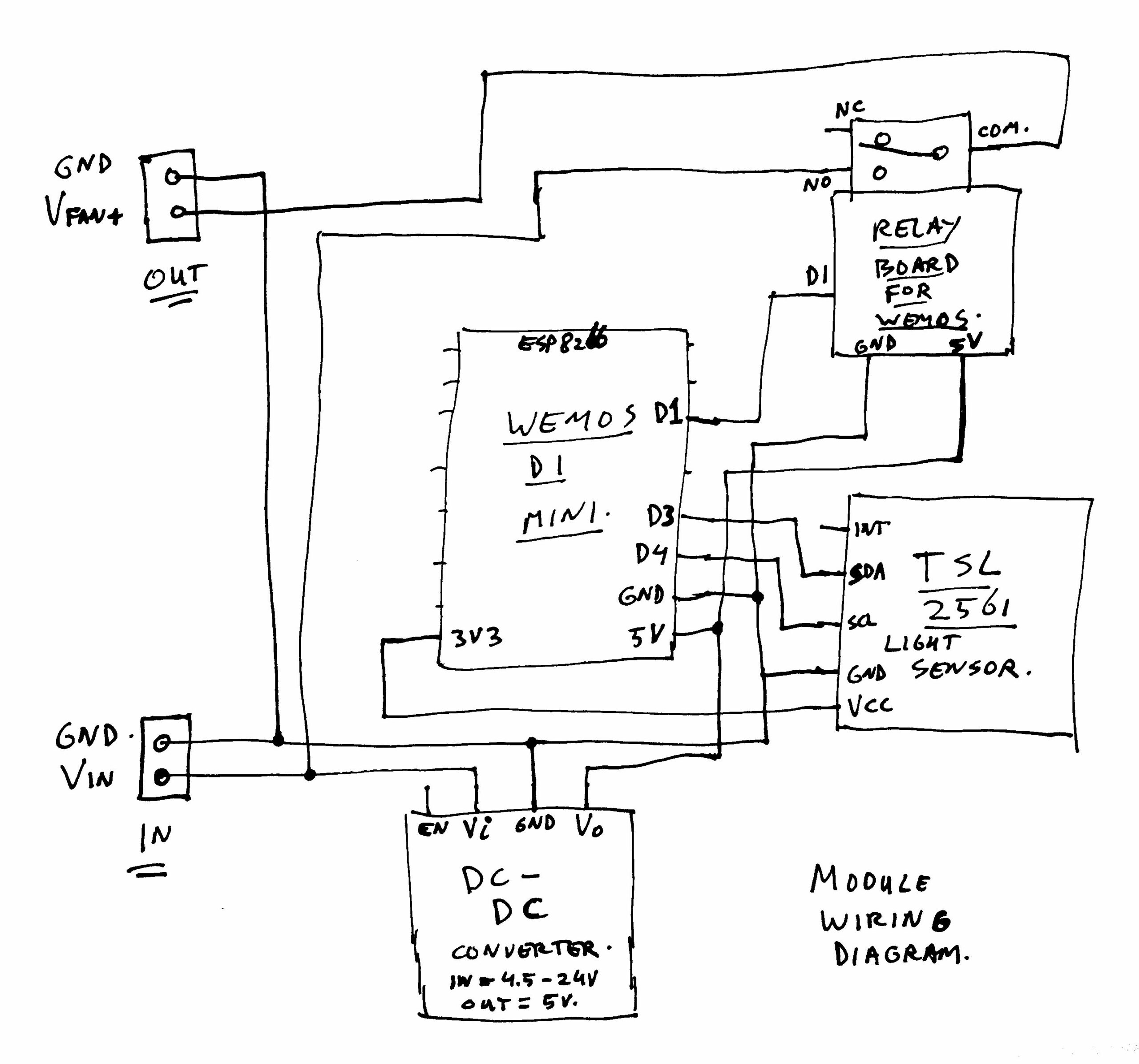
Wiring Diagram:
Source Code:
See GitHub for the full source: https://github.com/atkaper/esp8266-light-triggered-fan-timer
In the source, you can change some settings, between the lines marked with “start of settings” and “end of settings”. Things like your WiFi credentials, Over-The-Air update password and board name, timing values, your time-zone (not really relevant), NTP servers to use (also not important), which pins to use for the light sensor, and light detection level.
There is also this setting: ENABLE_AUTO_LUX_DETECTION_MIN_MAX, which if set to “true” will automatically configure the light detection level for you, by storing the min and max LUX value, and taking a spot 2/3 between that. However, it is best if you start with that to “true”, then turn on/off the light, and use a web browser to check what the detected light level is. Then change the config to set that level in LUX_LIGHT_DETECTION, and change ENABLE_AUTO_LUX_DETECTION_MIN_MAX to “false” to disable the auto detect. Why? Because ESP8266 modules tend to crash/reboot sometimes, which is not a real issue for a fan timer, but after a restart, it would not know the proper detection level, until you turn on/off the lights. Until then, if the default level is near the current level, the relay might start clicking on/off unwanted 😉 Ok, we could change the program to keep all disabled until the min/max were learned, but I did not do that. Sorry.
The source code itself is not really complex, and has a bunch of comments in there, in case you want to tweak it to your liking.
The program does expose a web-page, in which you can see the current state of the timer, and optionally override it’s state to turn the fan on or off with a simple click.
Here’s an example of the served web-page:
Time: Fri Mar 12 20:32:49 2021, NtpSync: 4.0 min ago, current lux: 1.0, compare >= 95.0 lux?, light: OFF, startFanAfterSeconds: 0, fanRunSeconds: 1671, fan: ON
ON | OFF
The bottom ON | OFF are the buttons to start/stop the fan. There’s no nice layout, as I do not expect anyone to use this. It’s mainly for debugging, and finding your initial LUX level detection values.
Product Titles / Search Terms:
As ordered on aliexpres (so they are weird long product titles):
- 1pcs/lot GY-2561 TSL2561 Luminosity Sensor Breakout infrared Light Sensor module integrating sensor AL
- 1Set One Channel Wemos D1 Mini Relay Shield Wemos D1 Mini Relay Module ESP8266 Development Board 1 channel
- ESP8266 ESP-12F WeMos D1 Mini Module WiFi Development Board CH340G Micro USB 3.3V Based On ESP-8266EX 11 Digital Pin
- Ultra-Small Size DC-DC Step Down Power Supply Module 3A Buck Converter Adjustable 1.8V 2.5V 3.3V 5V 9V 12V
– Current max 3A, average 2.1A
– Input voltage: DC 4.5-24V
Build And Product Images:
End Result – Sensor Side 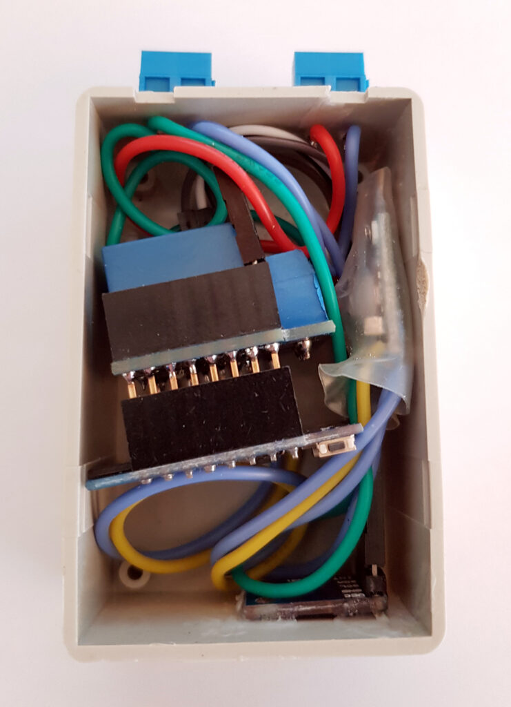
End Result – Stuffed-in-a-Box 
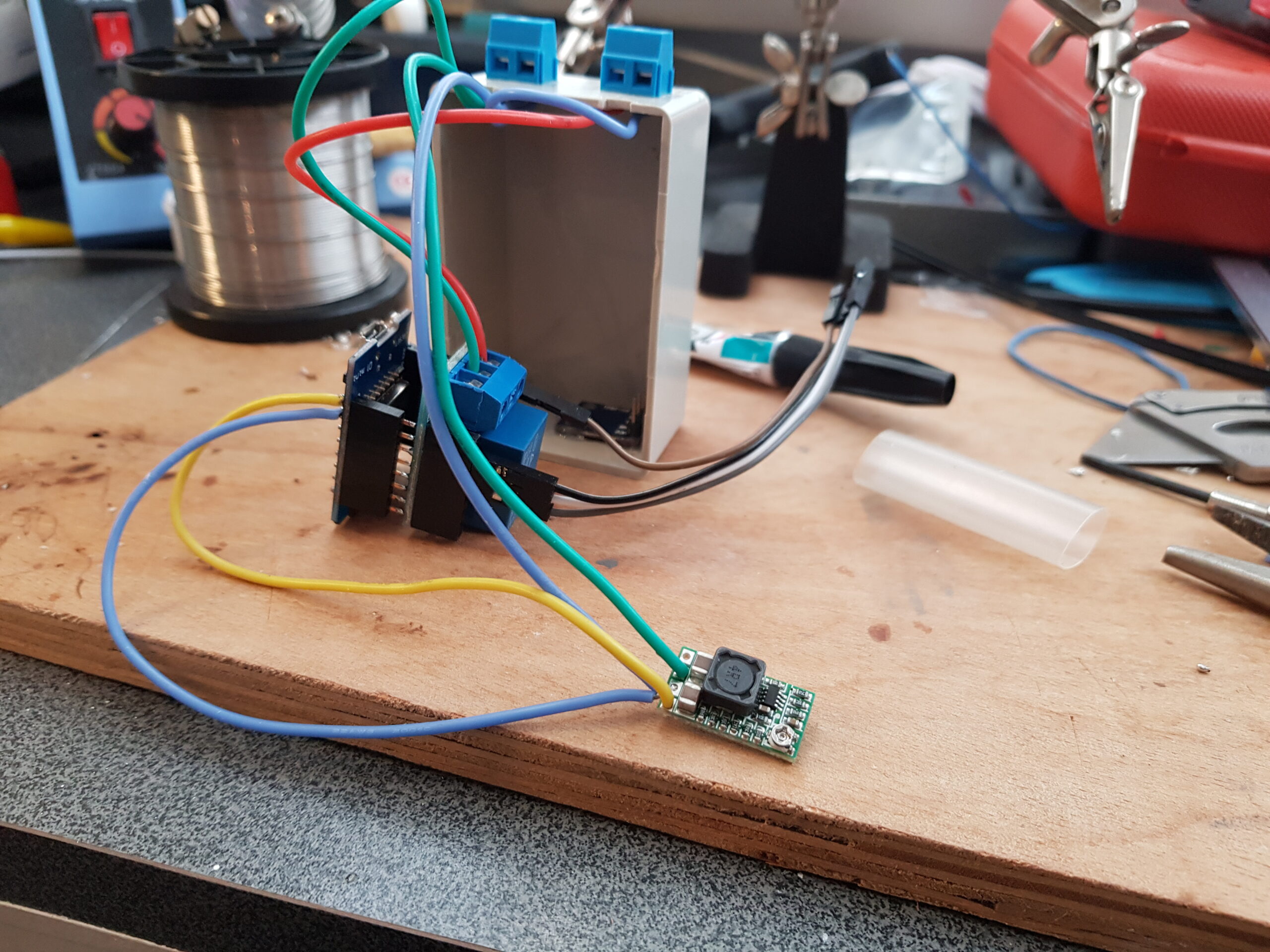
Some of the Wiring 
The Ultra Small DC-DC Conv 
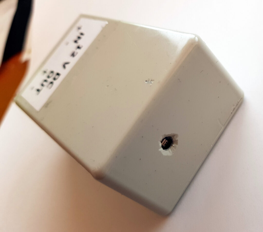
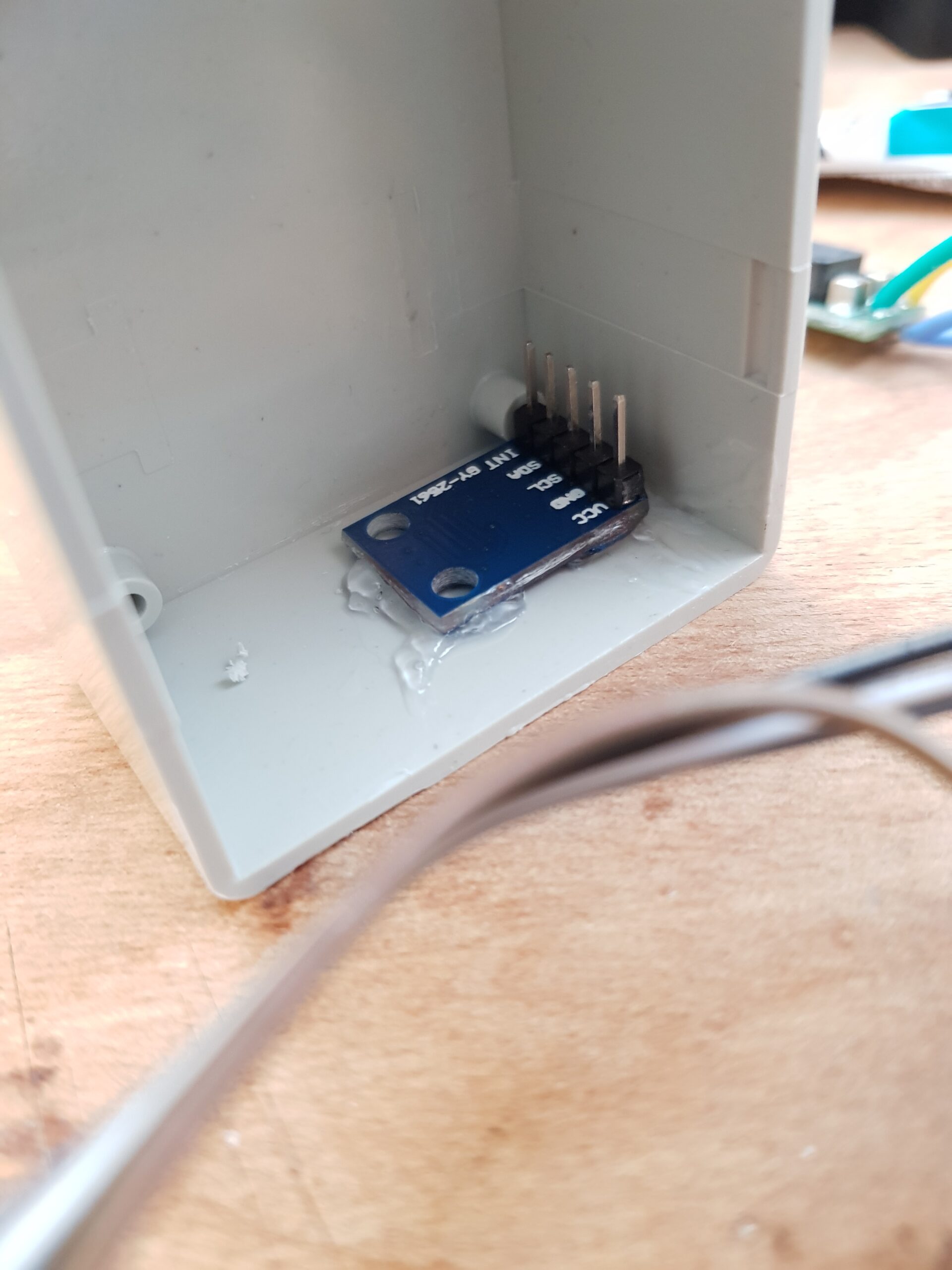
Gluing the Sensor in place 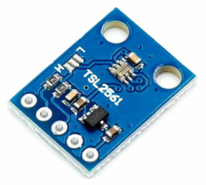
Light Sensor (top) 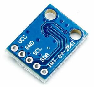
Light Sensor (bottom) 
DC-DC Converter 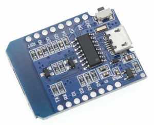
WeMos D1 Mini 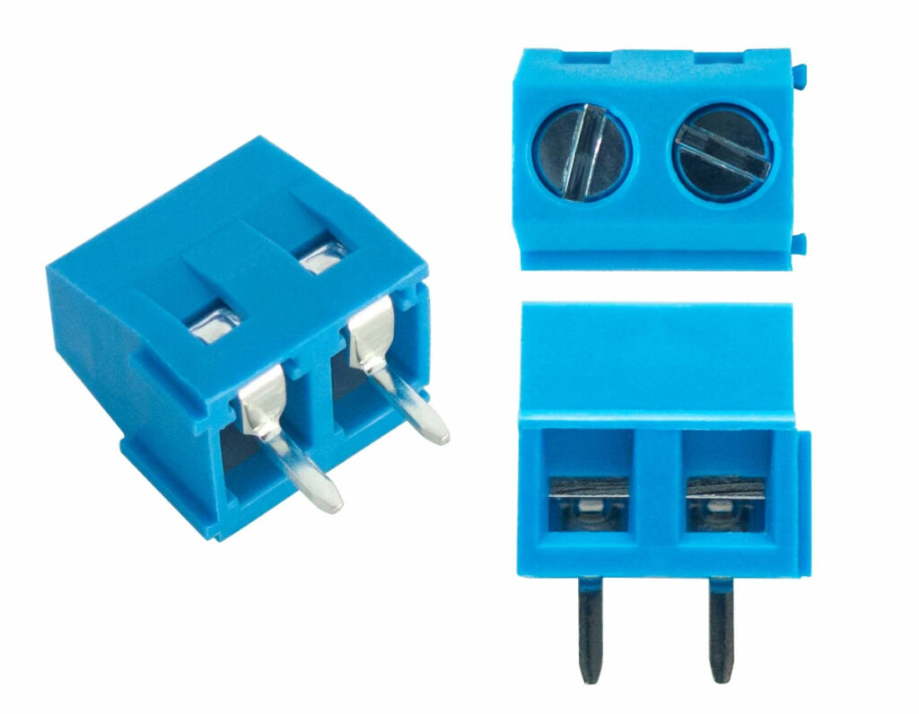
Terminal Blocks 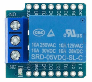
WeMos Relay Shield (top) 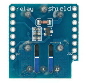
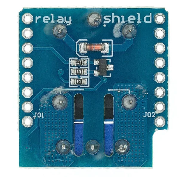
WeMos Relay Shield (bottom)


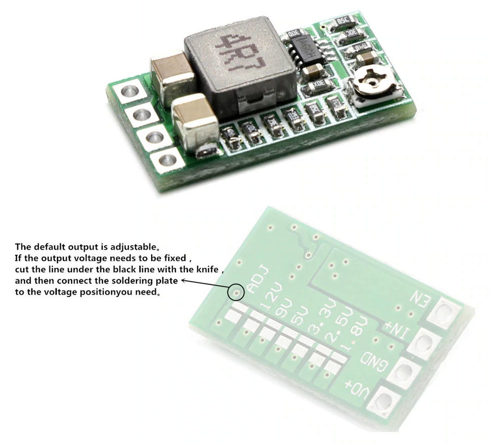


Both the WeMos Board and WeMos Relay shield come with connector strips, which you can solder on the boards to be able to stack them. The DC/DC converter can either be set to the proper voltage by using the potentiometer, or by cutting a trace, and soldering one of the voltage bridges at the bottom of the print. I did choose for that last one, in the hope to keep the voltage more stable. It however ended up a bit below 5V, but it still seems to work fine with it.
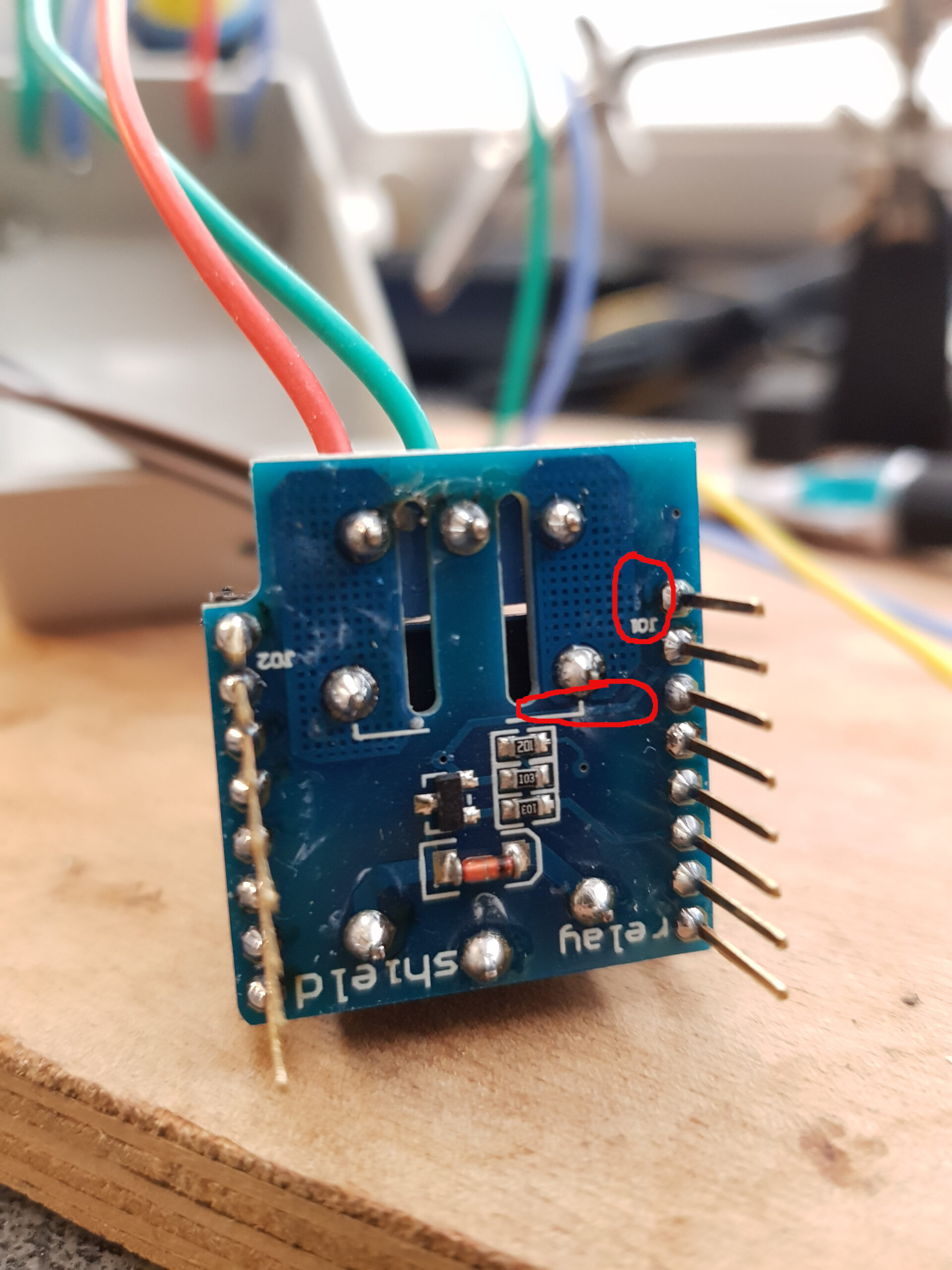
Warning:
In case you are tempted to use the relay shield to switch a mains power fan (240V/AC), please DON’T! In theory, the relay on the board is suitable for that, BUT… the printed-circuit-board as designed by the seller, does NOT have the proper trace clearance (in my opinion) between high and low voltage parts. See this image, the red circled parts:
Conclusion:
I did not do any attempt at making this thing any smaller, as my situation is that there is a cupboard next to the smallest room, and they are both connected to the same light switch. So the project box sits in that cupboard, connected to the FAN power line.
If you want this any smaller, you could go for a bare ESP8266 board, and use a smaller relay with a transistor, all put closely together. Or you could drop the relay, and just use a transistor or FET to drive the FAN. That would enable you to make it small enough to fit inside the FAN enclosure perhaps.
So, now just wait for the FAN companies to adopt my little controller board, and sell more luxurious versions of FANs 😉
Thijs, March 13., 2021.