Macro Keypad
I thought that since working from home those last two years, it would be a nice gadget to have a toggle button to enable/disable the microphone when using MS-Teams for online video meetings.
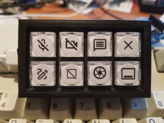
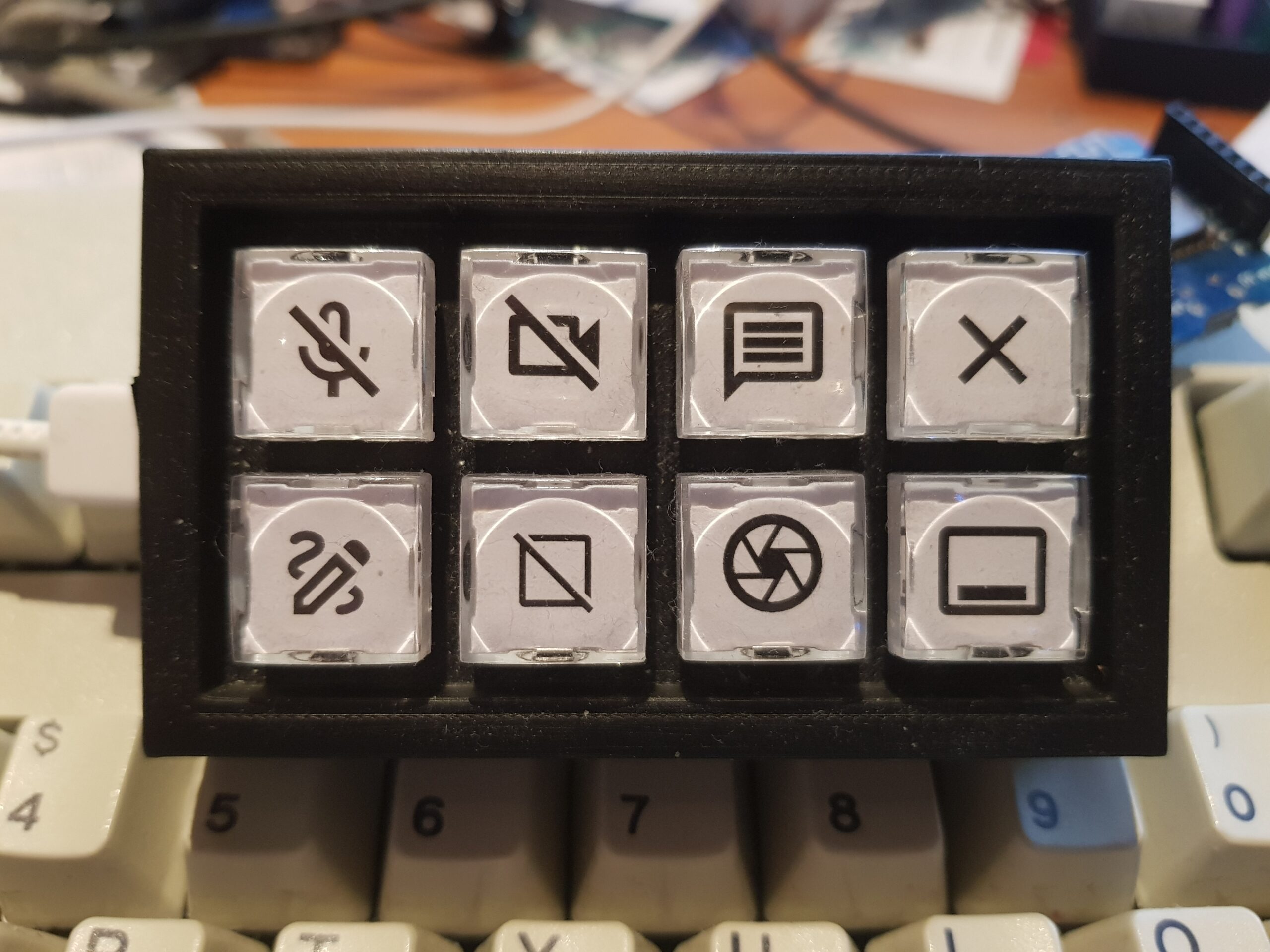
But a macro keypad with just one button is a bit silly, so I decided to go for 8 buttons. I did not really think too deep, and came to these functions for now:
- toggle microphone in ms-teams.
- toggle video in ms-teams.
- open a new chat message in ms-teams.
- exit new chat / exit video call.
- toggle drawing on screen on/off (this is drawing in a separate layer on top of everything, quite handy!).
- clear drawing from screen.
- region screenshot.
- open new terminal window.
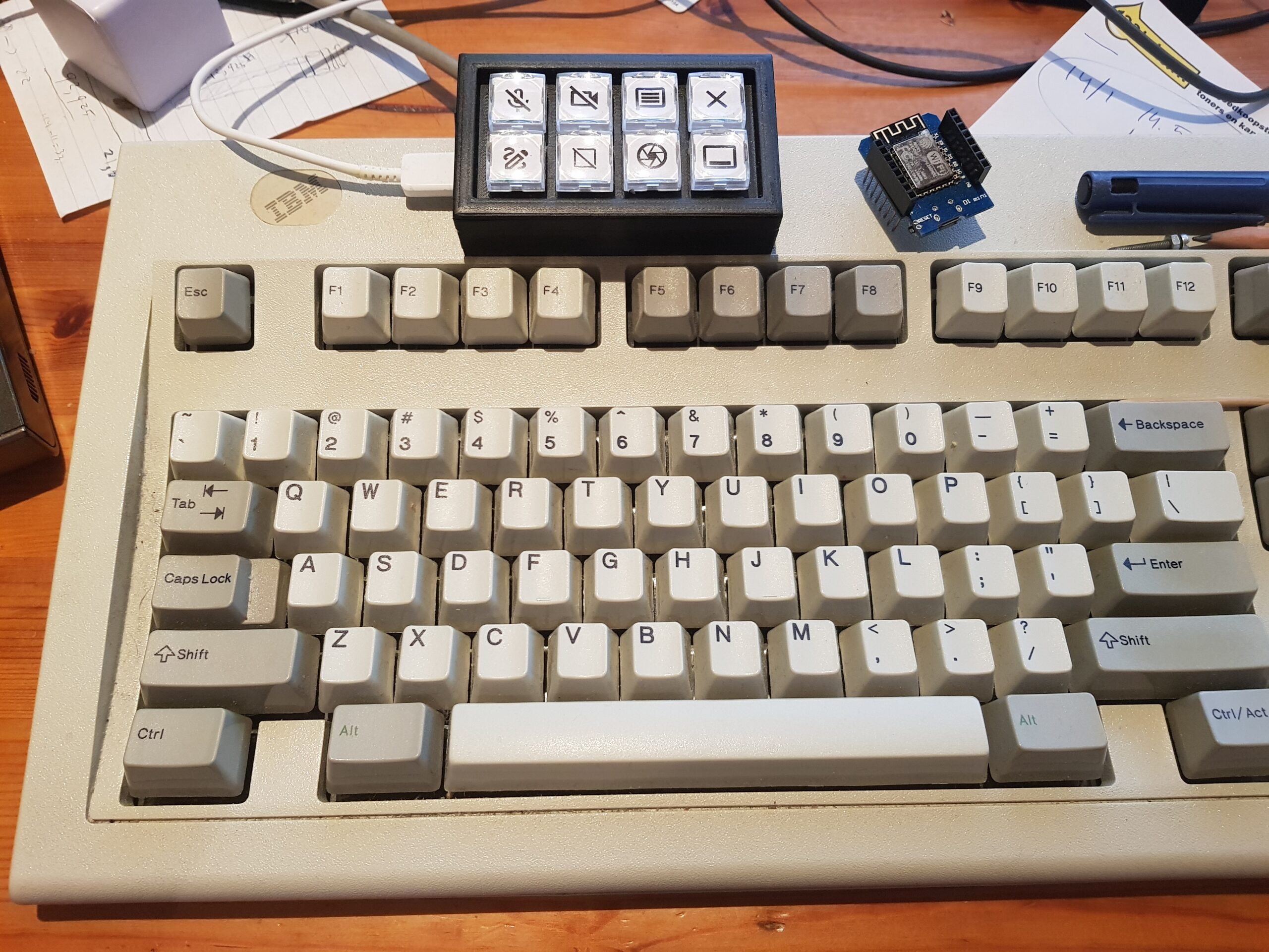
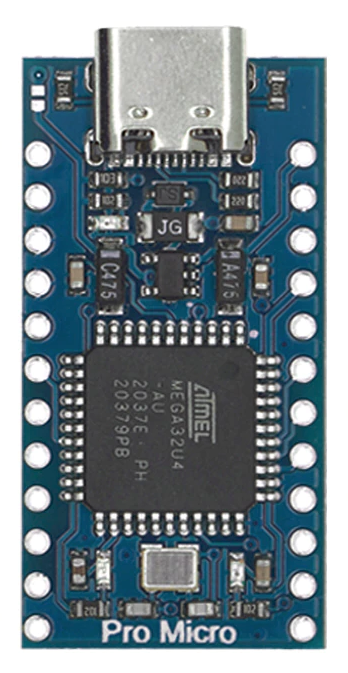
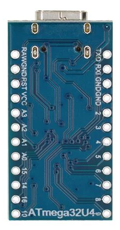
To get to the end result, I took a hand full of buttons (with a blue led in them), some wires, resistors, an ATMEGA-32U4 (Arduino Leonardo) USB-C micro-controller board, and we wired that all together, put it in a box, put some software on it, and all done!
Many macro keyboards do exist already; the unique selling point here is the possibility to control the LED’s inside the keys from a computer/macro script. So hitting the “region screenshot” button will enable the led, and when you are done with making the screenshot, the led goes off (and it was just fun to build).
Note: my daughter (22 years old) wanted to give soldering a try, so she did all of that, and she also did help out measuring the case sizing. I did the case design and printing, and the software.
The project files can be downloaded from GitHub: https://github.com/atkaper/macro-keypad
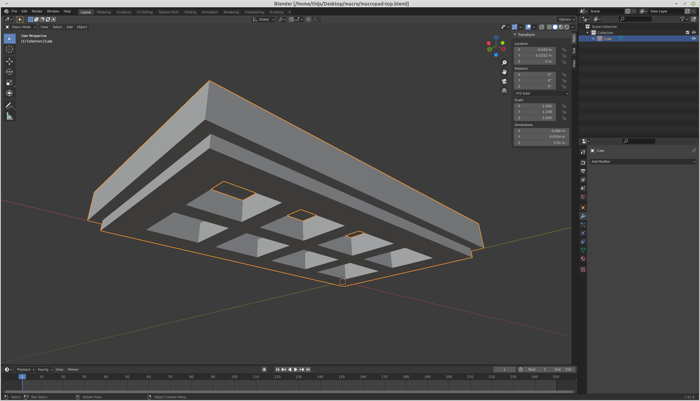
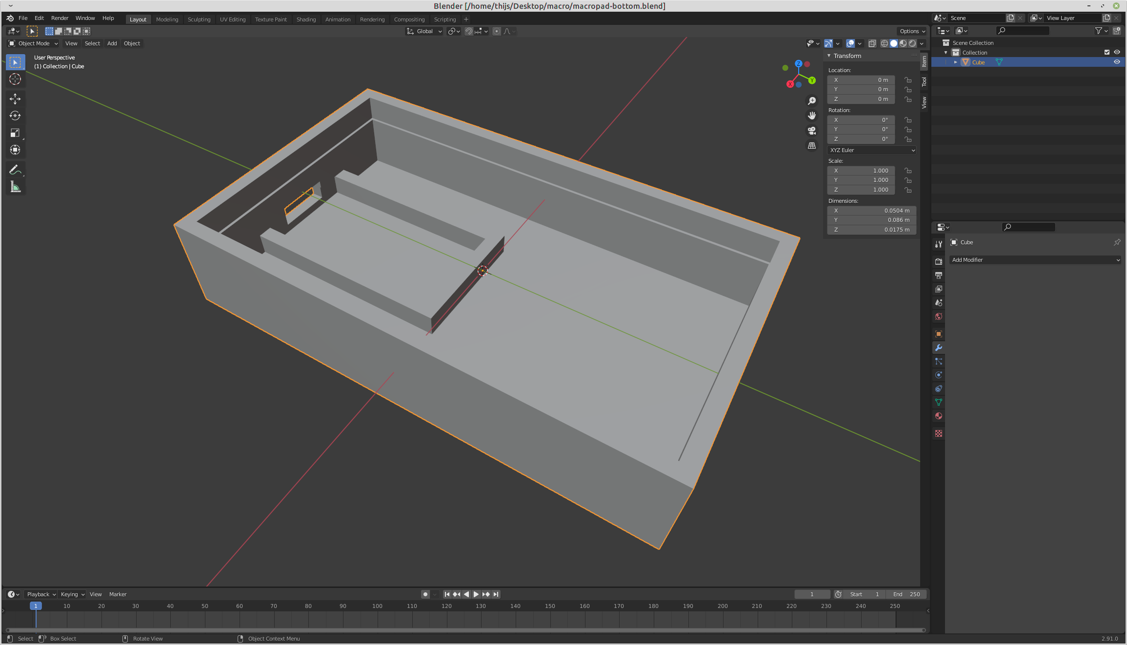
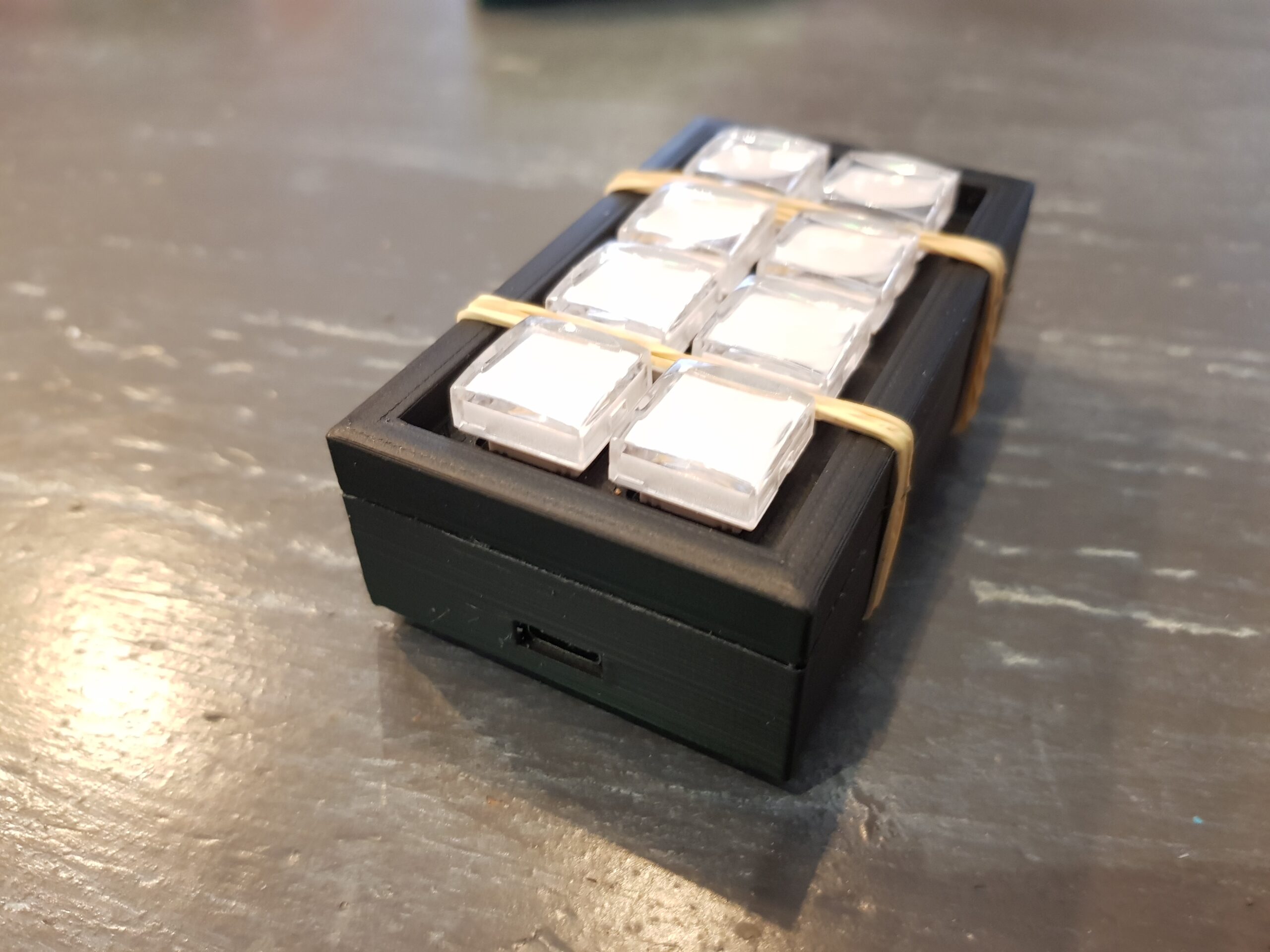
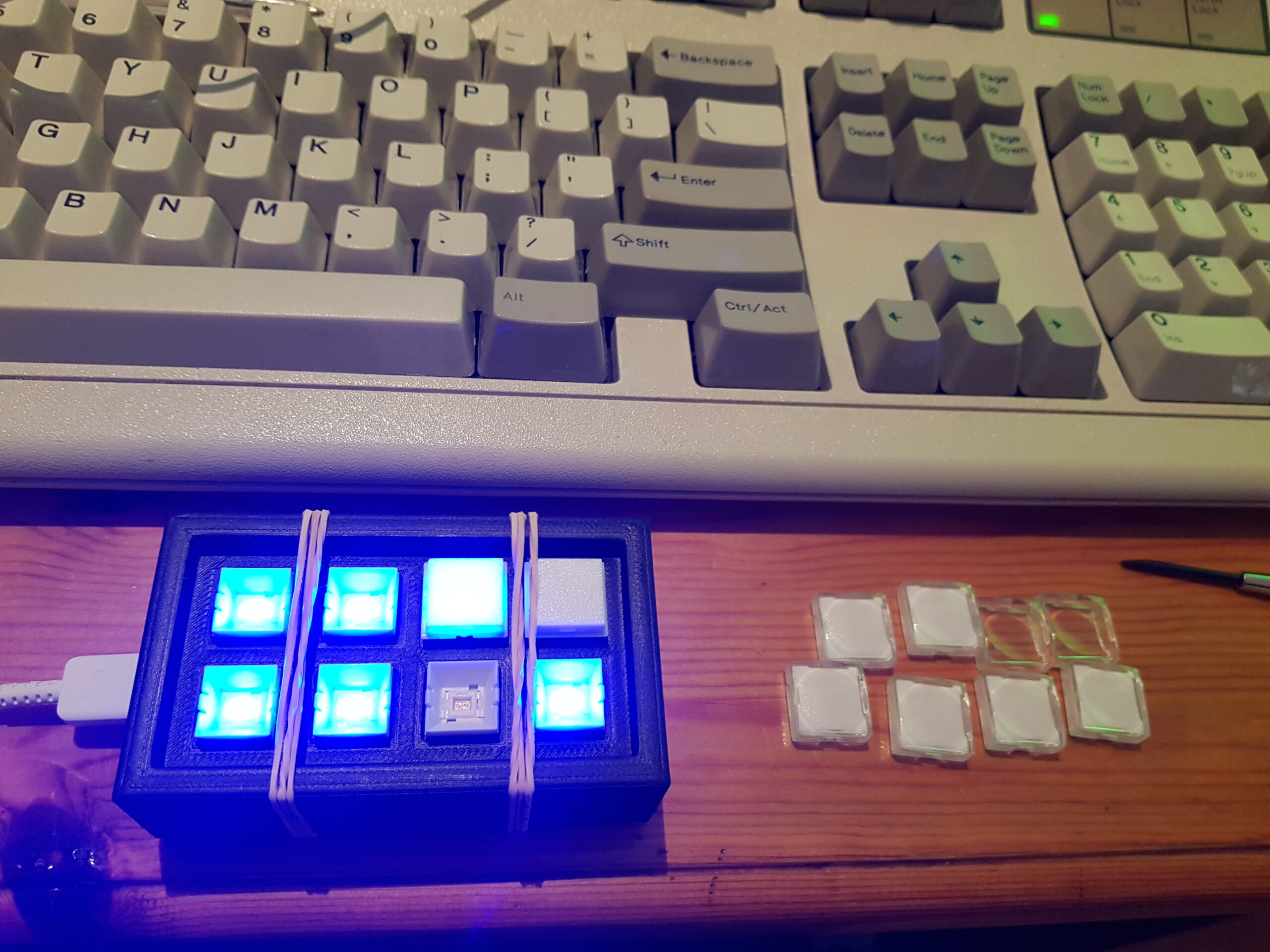
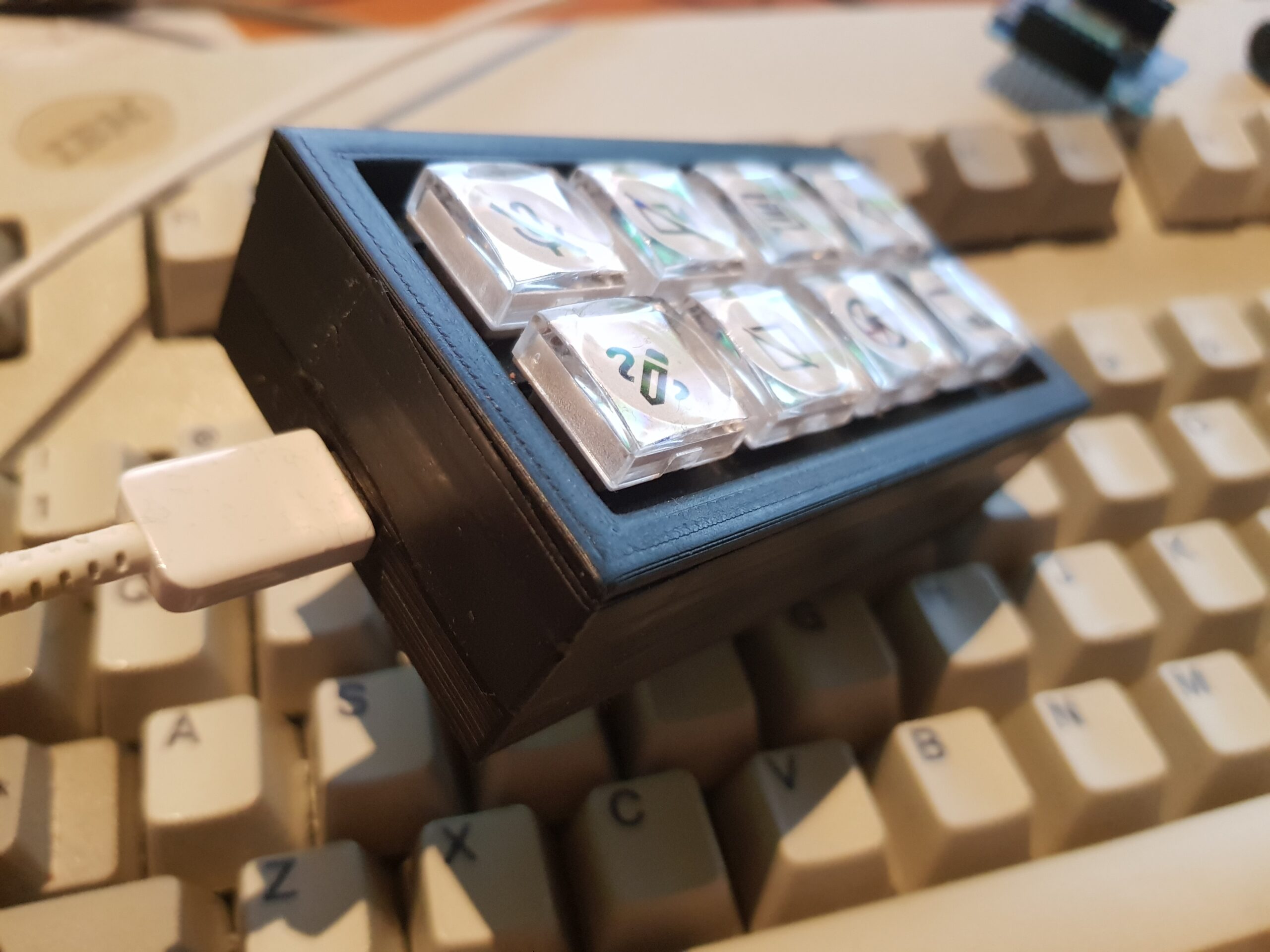
End result
Let’s start with images of the end result. My 3d printer does print a bit messy (not that smooth), but the end-result is good enough for me:
Components:
Let’s start with the components, and then go over to a simple schematic to tie them together:

Schematics
Since it was just a hand full of components (8 buttons, 8 resistors, 1 micro-controller, and some wires), I did not deem it worth to use a schematics design program 😉 So here’s some quick drawings [click to zoom]:
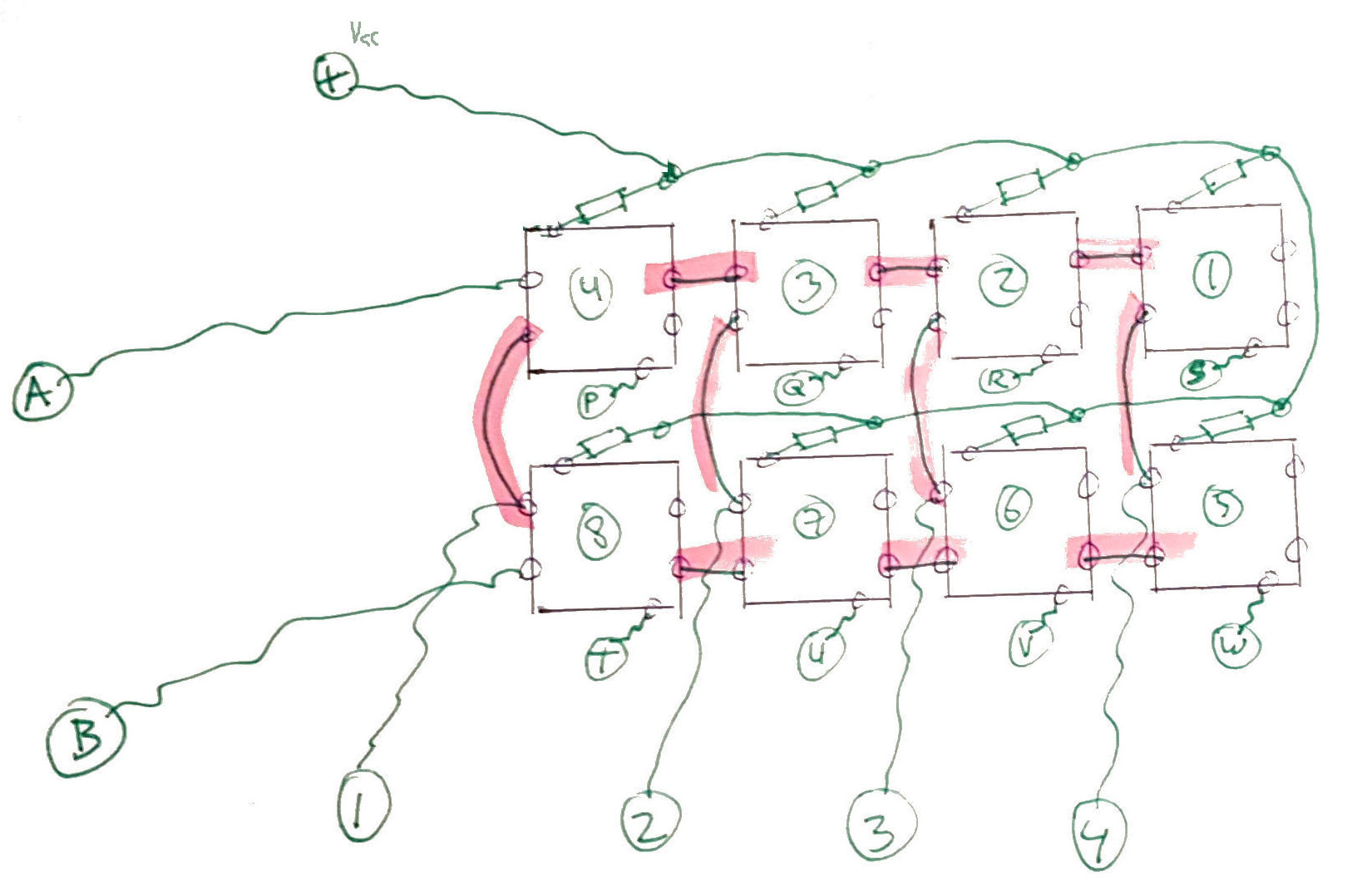
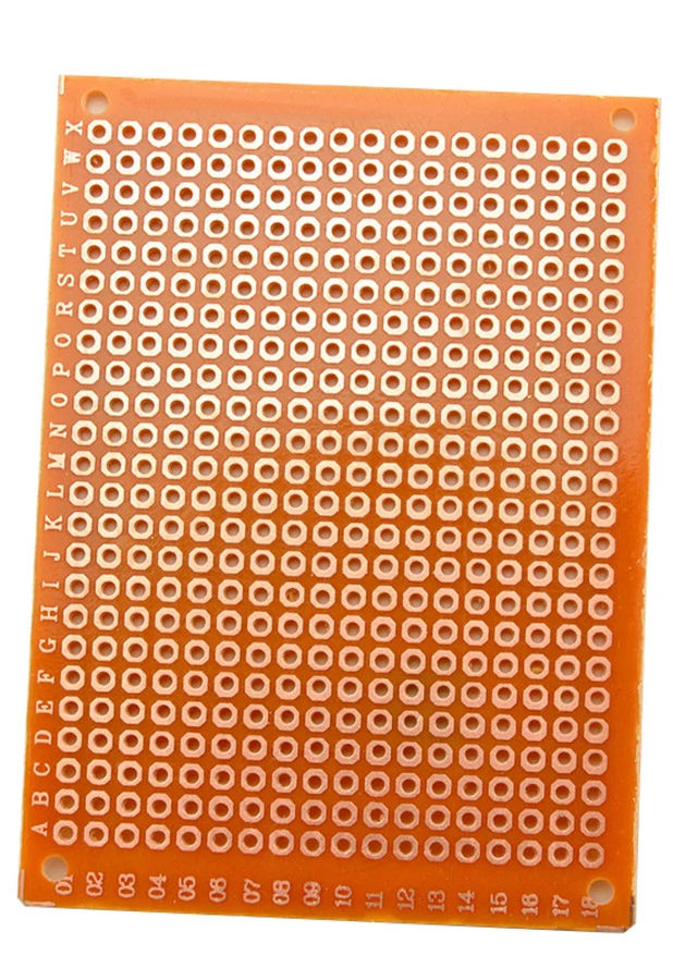
The top left image shows the bottom view of the buttons, with the pins where the resistors need to be connected (that’s on each positive [+] led pin). The component placement was directly translated onto a piece of simple experimenting through-hole printed circuit board (protoboard).
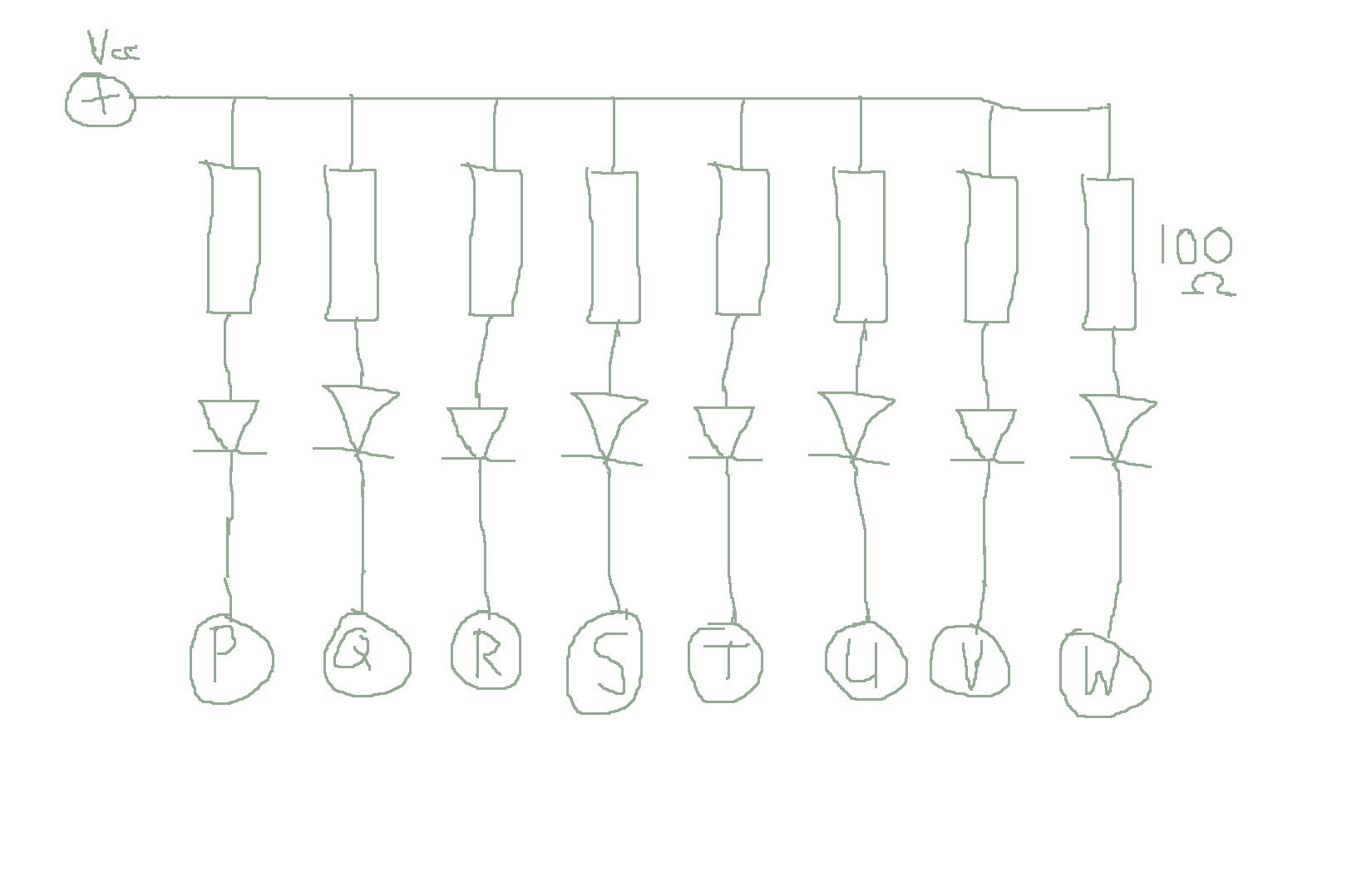
The top right image shows the schematics of how all led’s are wired with a resistor (each 100 Ohm) to the common + (Vcc) power line.
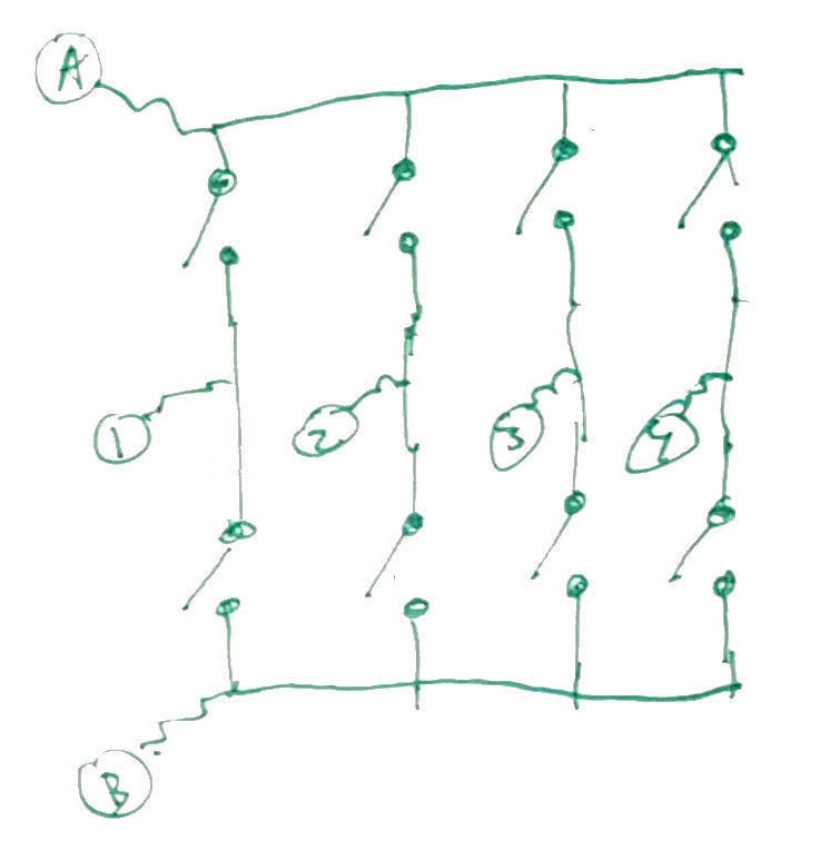
The bottom left image is the schematics of the key matrix. Wire “A” is the top-row common wire, wire “B” is the bottom row common wire, and wires 1/2/3/4 are the columns. I did not add diodes in the matrix, because I am not planning on pressing multiple keys at the same time. A real keyboard will have a diode at each matrix key intersection, to allow proper pinpointing of the pressed key when more than one is pressed.
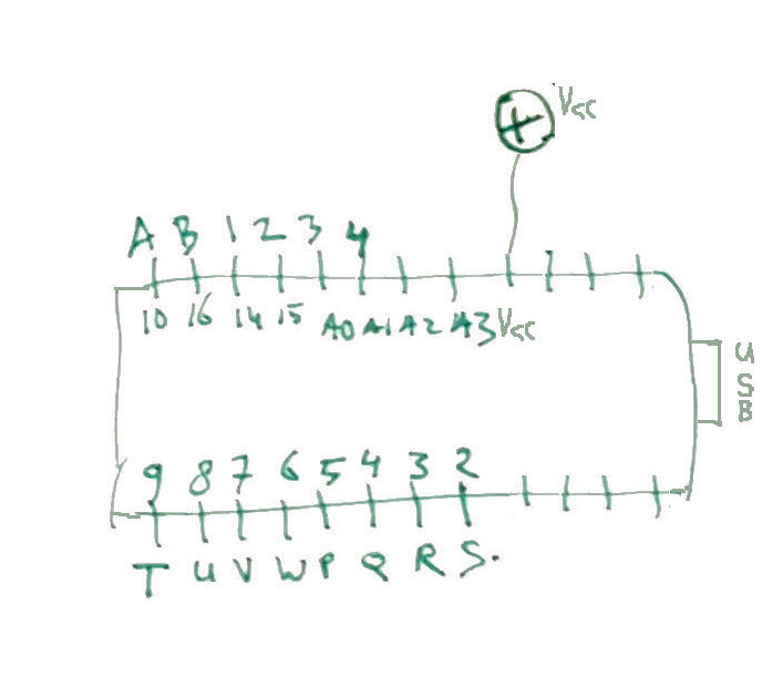
The bottom right shows the pin’s of the micro-controller (bottom view, controller pin names inside the box), where I added a letter or number (or +) on the outside of the box to indicate which wire goes where.
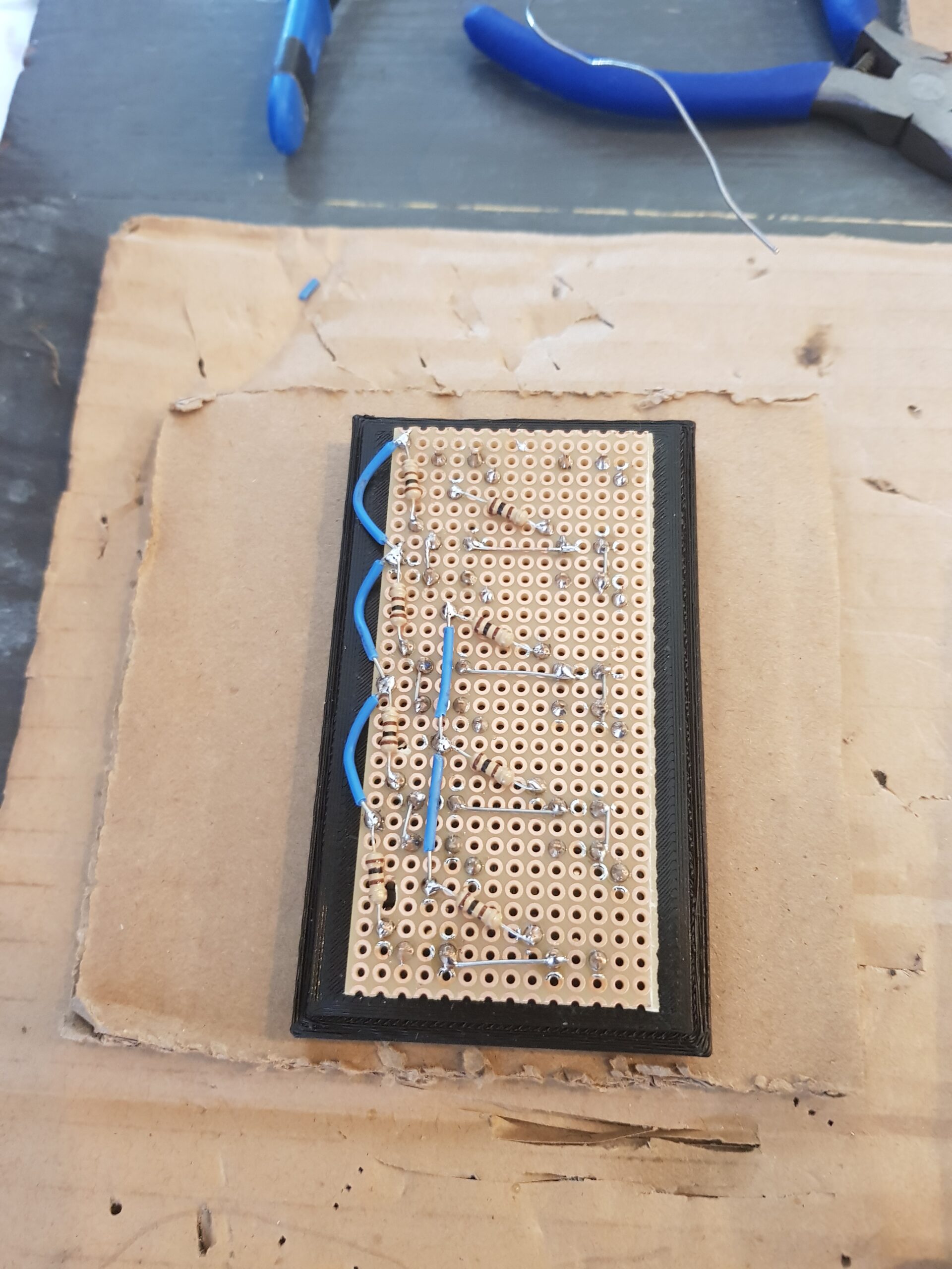
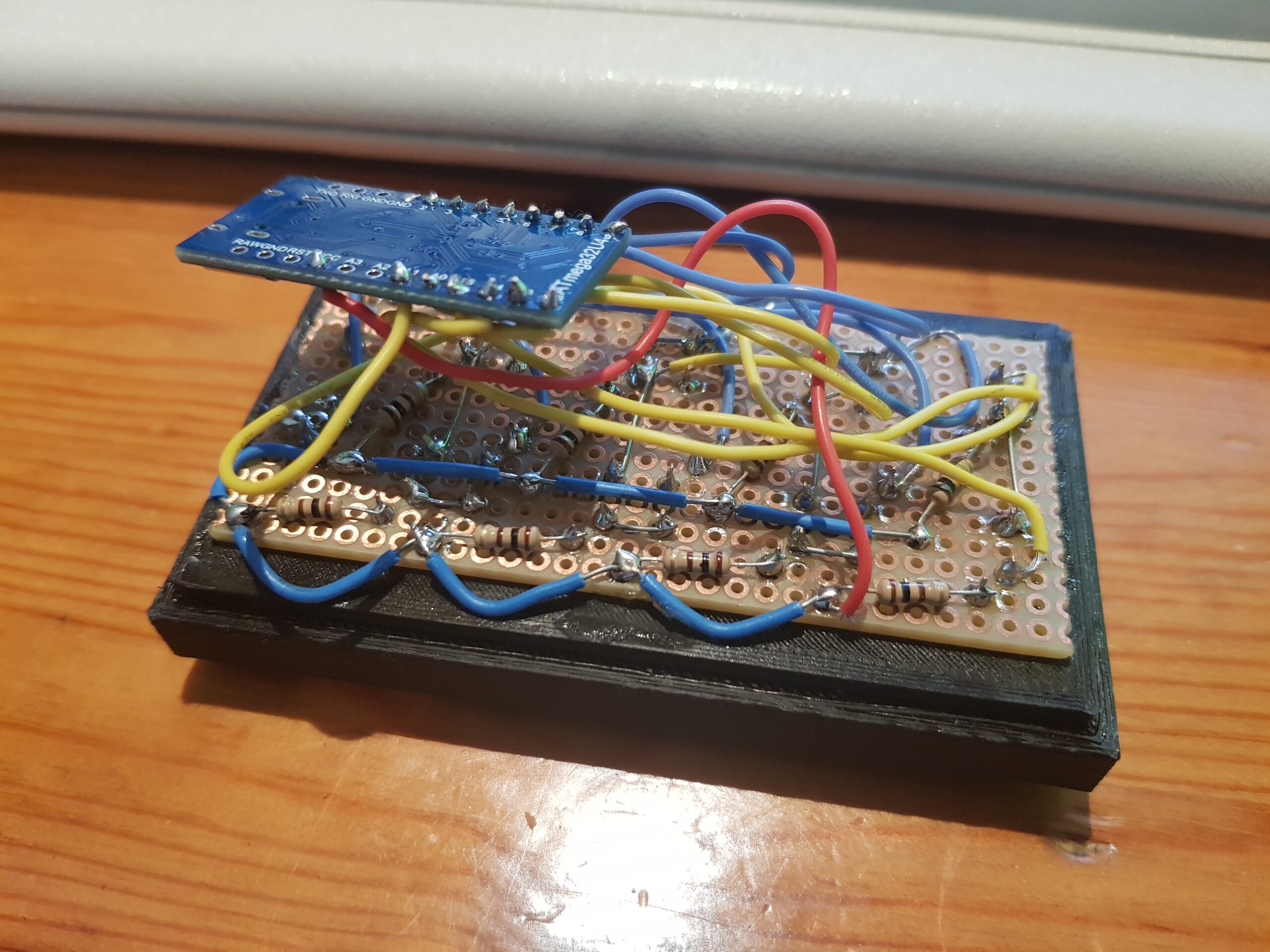
Building the electronics
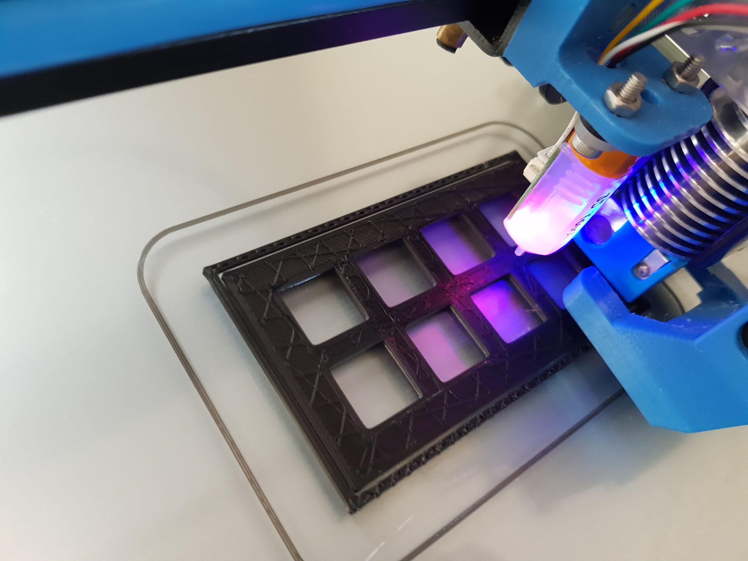
I’m actually skipping a step here (or mixing up the build order). In the images you see a piece of black plastic, that’s the top cover of the case. We started by measuring where all buttons would end up, then designed and printed the top case. The buttons sort of have a mushroom shape (wide cap, small base), so we stuck them through the top cover, and then soldered them to the print. Quite a bit later I found out that you can take off the top of the buttons 😉 Being able to take off the clear cap of the buttons was known from the start, but taking off the part between the cap and bottom was a surprise finding.
Here some images of the soldering job (done by my daughter, as a first soldering thing ever for her – turned out quite well!):
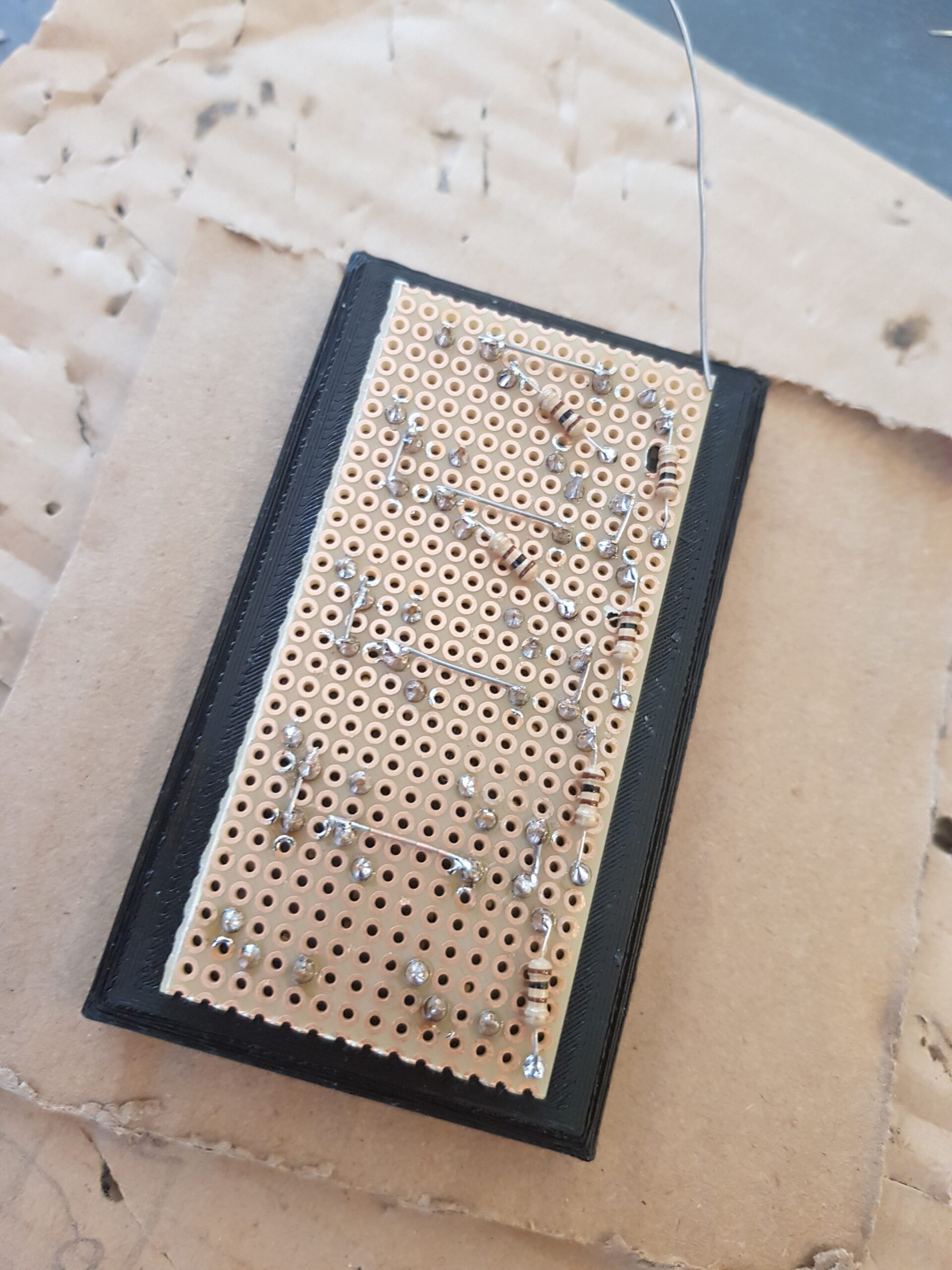
Order of soldering was:
- first the buttons,
- then the button cross-link (bare) wires to connect the matrix rows and columns,
- then the resistors,
- then the resistor common (+/Vcc) wires,
- and lastly connect everything together to the controller using longer wires.
Long wire colors: For the key-matrix we used yellow wires, for the led wires we used blue, and for the led common (+/Vcc) to the controller a red one.
Note: for the sharp viewers – some wires have been stripped a tiny bit longer than I would have done, but it is not touching anything it should not, so it’s fine in this case and does no harm.
Designing the case
I’m not a master 3D designer yet. In blender I mainly use cube / box / bar shapes, and take the boolean operator to cut holes and combine parts. I heard from a friend of mine that I should move over to FreeCAD, as that works much better for technical drawings, using proper measurements and parameters to resize stuff.
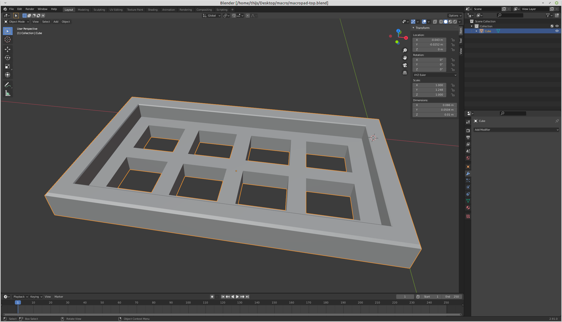
The blender files, and the exported STL files have been attached to the appendix section at the bottom of this post.
One word of warning: the bottom case part was a tiny bit too tight fitting (= not fitting), so I did scale that one up by a fraction during slicing from stl to gcode in Cura. We did create the top around October 8, 2021, and the bottom on the 29th of that month, so that’s a couple of months ago already 😉 So I do not remember the actual scale factor.
Putting it all together
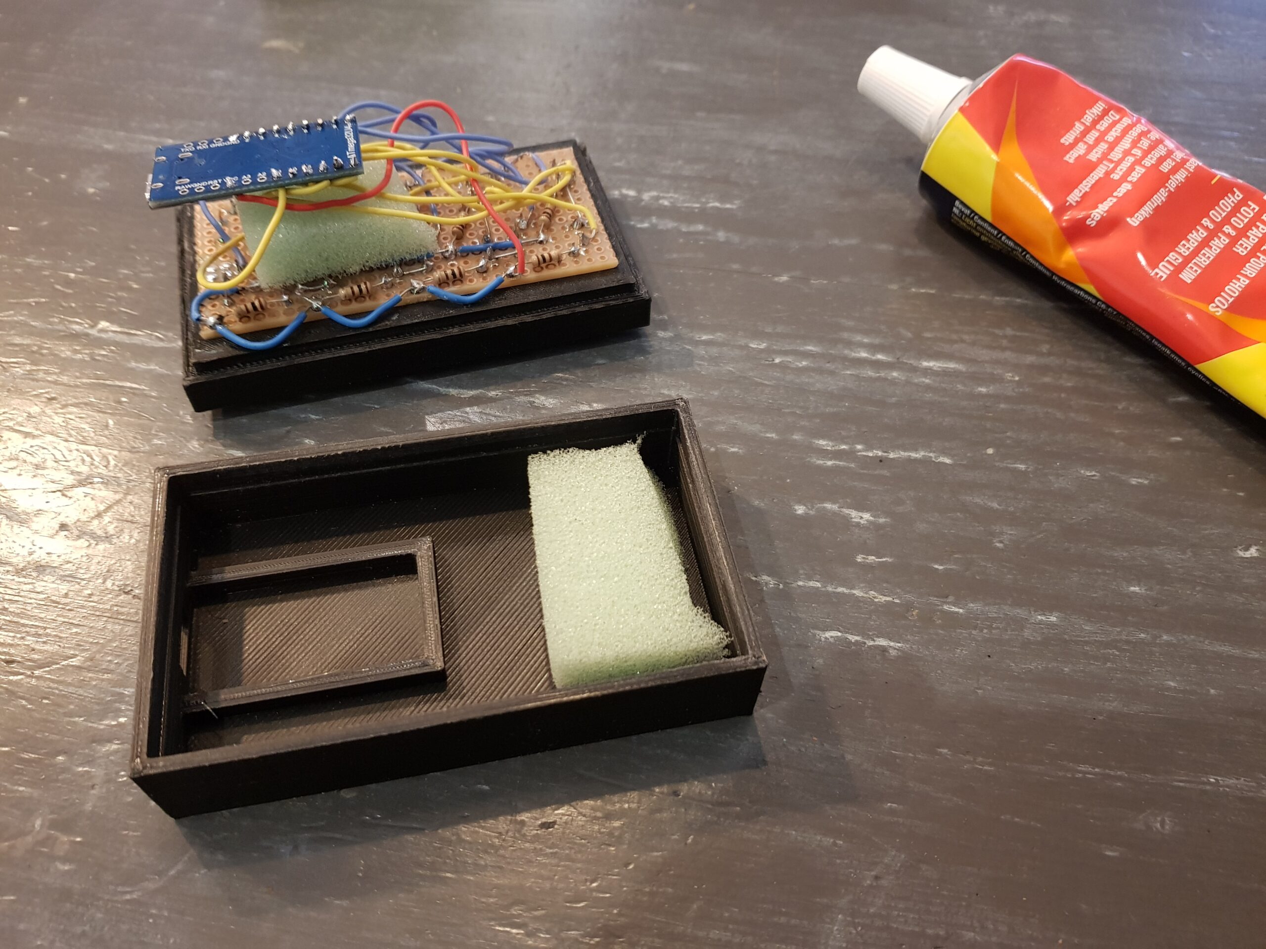
The protoboard has been glued with 6 drops of superglue to the top cover (careful to not get any superglue inside the switches), but just in case those will break free, I added some sponge’s in the case to keep everything in place anyway. As I do want to be able to open up the case in case of problems, I thought it was a good idea to use photo glue to glue it shut. Ok, that’s a bad choice 😉 So I ended up wrapping a bit of black electrical tape around it. In Dutch we would call that “Houtje touwtje”. If you plan on building a macro pad also, then either just use superglue to close it up, or just redesign the case to have little notches and slots in the top and bottom case parts, which click together. That would be much neater / better!
To print little icons to put between the clear cap and the white middle bit, I used Google Fonts Icons (https://fonts.google.com/icons). On that site I just browsed around a bit, and found some icons which would cover the meaning of each macro key. These were just printed using a laser printer on a piece of paper, and cut into parts. The end result looks quite alright to me. A file with the used icons is attached to the appendix section at the bottom of the post. But I guess that anyone building a macro pad will need their own set of icons.
Creating the controller software
For the micro-controller software, look at this file: https://github.com/atkaper/macro-keypad/blob/main/MacroKeyPad/MacroKeyPad.ino
The used Arduino Leonardo ATMEGA 32U4 compatible development board (SparkFun Pro Micro – Clone), can be programmed in C, using the Arduino-IDE (see https://www.arduino.cc/). The controller supports emulating USB devices like keyboard, mouse, joystick, and others. For this project I just used the USB HID Keyboard functions, using the “Keyboard” library.
To get input to send as USB Keyboard commands, I did use the “Keypad” library. It does allow you to make a matrix of rows and columns to connect switches to, and call a library function to get the pressed key.
Next to these two, I thought it would be nice to make the key mappings configurable, and have two keymaps in memory. You can switch between the keymaps by sending a command to the controller. The configuration is stored in the on board EEPROM to get picked up after a new power-up.
To be able to query and change configurations, and to be able to influence the LED states, the controller keeps an open serial port (USB) device, next to the keyboard (USB) device. So the controller has 2 USB connections in use at the same time.
For configuration purposes I did build in a little command interpreter in the controller.
Here is the set of supported commands:
help                    : [or ?] show this help
version                 : [or v] show the macropad version
getled <NR>             : [or g] get led <NR> state (return 0 for off or 1 for on)
toggle <NR>             : [or t] toggle led <NR> state (<NR> is 1..8)
on <NR>                 : [or e] turn led <NR> on/enable (<NR> is 1..8)
off <NR>                : [or d] turn led <NR> off/disable (<NR> is 1..8)
flash <NR> <MS>         : [or f] turn led <NR> on, sleep <MS> milliseconds, turn off, and sleep same
                                 time again (<NR> is 1..8, <MS> is 10..500)
animation               : [or a] run startup led animation
usemap <NR>             : [or u] enable keymap <NR> (<NR> is 1 or 2)
configtoggle <NR> <SET> : [or c] configure key led toggle for key <NR> (1..8), <SET> is one of [t,e,d,f]
                                 where flash will be 150ms
showsettings            : [or s] show settings
setkeycode <NR> <CODE>  : [or k] set key code of key <NR> (1..8) to <CODE> 0..255
setkeychar <NR> <CHAR>  : [or h] set key character of key <NR> (1..8) to <CHAR> (a single char)
persist                 : [or p] write config to EEPROM (use if you changed keys or configtoggles)
load                    : [or l] load config from EEPROM (automatically done on each startup)
The commands all have a long form, and a one character version to save some typing.
Here an example output of the “showsettings” command:
map 1 active
key 1, led: off, ledconfig: t, keycode: 240
key 2, led: off, ledconfig: t, keycode: 241
key 3, led: off, ledconfig: f, keycode: 242
key 4, led: off, ledconfig: f, keycode: 243
key 5, led: off, ledconfig: t, keycode: 244
key 6, led: off, ledconfig: f, keycode: 245
key 7, led: off, ledconfig: e, keycode: 248
key 8, led: off, ledconfig: f, keycode: 249
This shows you the current led state, and the ledconfig and keycode. The ledconfig can have 4 settings:
- t = toggle led between on and off when key pressed.
- f = flash led on/off (on = 150 ms, off = 150ms) when key pressed.
- e = enable led when key pressed.
- d = disable led when key pressed.
The keycode is either an ascii-code value (e.g. 65 = A), or a special keyboard code. Search your system for a file called “Keyboard.h” or look at this GitHub file: https://github.com/arduino-libraries/Keyboard/blob/master/src/Keyboard.h for the mapping from KEY_XXX to a HEX code (1 byte). If you translate the HEX to decimal, you get the keycode to use. Example: KEY_F13 = 0XF0 = 240. You can use the “setkeycode” command to redefine keys, and then store those using the “persist” command.
If you are interested to see how the controller software is build up, you can have a read of the source code. I did add many comments in there to explain what every bit does.
See the README.md file for some clues on how to compile this and how to get it inside the controller. And of course use internet search in case compilation or set-up of the Arduino-IDE gives any difficulties ;-).
The PC software and setup
I use the key pad on Linux Mint (now at 20.2), with XFCE4 as windows manager. There are two scripts delivered with this project in the Linux-Tools folder: https://github.com/atkaper/macro-keypad/tree/main/Linux-Tools
You should be able to use the keypad on Windows or MacOS or other Linux flavors also. In that case one or both of the files probably won’t work. But for the Linux people here’s an explanation (and the python script might work on more systems):
The “key-macros.sh” file (https://github.com/atkaper/macro-keypad/blob/main/Linux-Tools/key-macros.sh) is a simple Bash script, which I use to execute key actions. The actions are for example:
- remember the current active window (uses xdotool Linux command)
- put an application window in focus, for example MS-Teams (uses wmctrl Linux command)
- send some keys to the active window (uses xdotool Linux command)
- restore focus to the window which had it before sending the keys (uses wmctrl again).
And there are simpler ones, just sending a key command to the system (toggle drawing on screen for gromit-mpx), or making a region screenshot using xfce4-screenshooter.
Also one of the examples makes use of the “send-macropad-command.py” script to turn off one of the LED’s on the key-pad. The key I use to make a screenshot enables the LED, and when the screenshot is done, the Bash script turns the LED off again. The LED stays on while selecting the screen area.
If you have a different Linux window manager, or a different flavor of Linux, you might need to alter quite some commands in the script to get similar results. But you can use it as an example anyway.
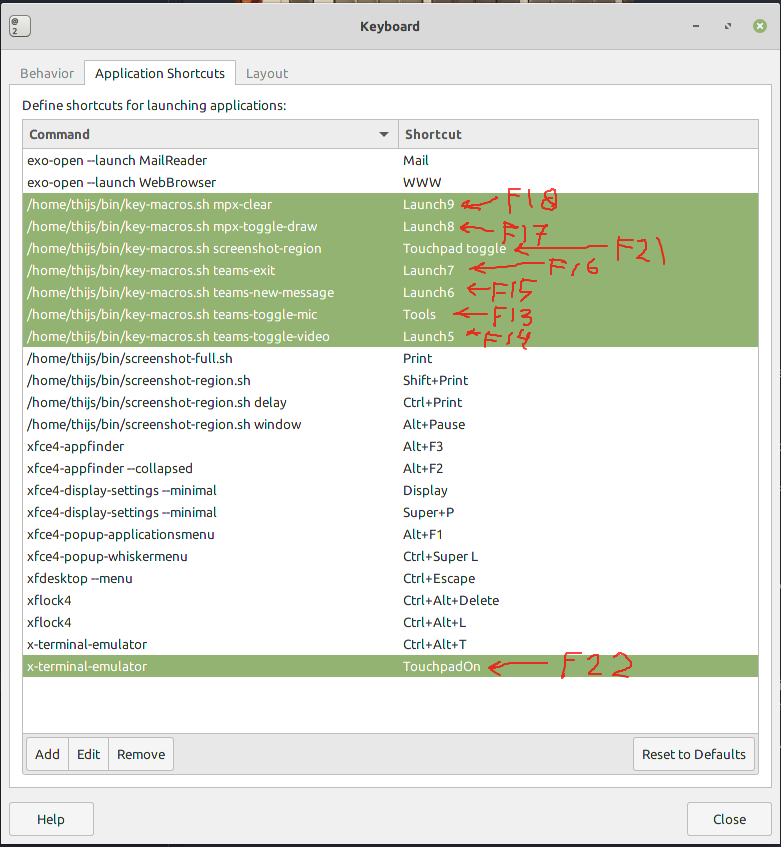
In my Linux I used the standard “Keyboard” configuration GUI to connect the key-pad keys to the Bash script. See this screen-print for the used mappings of F13..F18, and F21,F22 on my machine:
The second file in the Linux-Tools folder is “send-macropad-command.py” (https://github.com/atkaper/macro-keypad/blob/main/Linux-Tools/send-macropad-command.py). This is a (python 3) command line tool to “talk” via the USB Serial port to the controller, to change and query it’s configuration and LED states.
Here’s the help text from the tool:
$ send-macropad-command.py -h

usage: send-macropad-command.py [-h] [-i] [-v] [-q] [-l] [-t timeout] [-b bps] [-d device | -a matchwords] [command [command ...]]

Send command to macro keypad

positional arguments:
  command

optional arguments:
  -h, --help            show this help message and exit
  -i, --interactive     interactive mode (end with "exit" or ctrl-d)
  -v, --verbose         verbose / debug mode
  -q, --quiet           quiet / silent mode
  -l, --list            list serial ports
  -t timeout, --timeout timeout
                        time to wait for macro keypad to send a response to the command (default 0.1, if partial or no response, change to 0.2 or higher)
  -b bps, --baud-rate bps
                        baud rate, not interesting for atmega-32u4, but might be for others (default 115200)
  -d device, --device device
                        serial device to use (example /dev/ttyACM0)
  -a matchwords, --autodetect matchwords
                        auto detect serial port hwid/description words (default: 1B4F:9206 SparkFun)

Note: if you use the 'f' or 'flash' command, you need to increase the timeout if you also
need a response to be read. Count each flash time double (one for on, one for off time).

Examples:
send-macropad-command.py -v -l                       # debug port autodetection
send-macropad-command.py -a "9206 hidpc" -l -v       # change auto detect keywords to find proper macro pad device
send-macropad-command.py help                        # get command help
send-macropad-command.py -t 0.3 help                 # get command help, use increased timeout on slow computer
send-macropad-command.py -t 0.5 t 2 f 1 200 e 2 g 1  # toggle 2, flash 1 for 200ms, and turn on 2 after that, read 1
send-macropad-command.py -d /dev/ttyACM0 t 1         # toggle led 1, use device /dev/ttyACM0 instead of autodetecting the device
In essence it is a tool which sends anything you put as plain command line arguments (not the stuff starting with a -) to the key-pad controller. It first tries to auto-detect which serial device to use.
If serial auto-detect does not work, then execute the command with the “-l -v” options. The -l will list connected serial ports, and the -v will show debug information. From this step, you can either choose to use the “-d” flag for all next commands to just manually choose which device to use, or you can look at the description and hwid of the listed serial devices, and come up with some keywords from there which uniquely identify the proper port to use. Those keywords can be passed in with the -a command. You do need to put quotes around the keywords, like this: -a “keyword1 keyword2 keyword3 …”.
The tool also has an -i “interactive” option, which effectively turns it into a (line buffered) terminal emulator to keep an open line with the controller, to play around with the controller commands.
Just as the Arduino source, also this python source has many comments in the code, to explain what is happening.
Note: if you do not have read/write access to the serial device, add yourself to the proper group:
$ # Check the group you need (this normally will be "dialout"):
$ ls -la /dev/tty[AU]*
crw-rw----+ 1 root dialout 166, 0 jan 30 10:36 /dev/ttyACM0
crw-rw----+ 1 root dialout 188, 0 jan 30 10:36 /dev/ttyUSB0

$ # Add your user to the group (after this, log-out and log-in again to activate this)
$ sudo usermod -a -G dialout $USER

$ # You should see your username at the end of the line here:
$ grep dialout /etc/group
dialout:x:20:thijs
Tool demo:
Conclusion
A nice project to do, quite useful 😉 My initial idea of having macro buttons for MS-Teams chat stuff appeared to be not that heavily used by myself. The microphone toggle occasionally yes, the video toggle, new chat, and exit buttons not so much. The most used keys for me are the bottom row first 3 – drawing-on-screen / clean-screen-drawing / region-screenshot. I guess I can start thinking of 4 new functions to put on the 4 most unused buttons. At least everything is configurable, and the symbols behind the key caps can be replaced.
Note: if you want to use this macro key-pad on Windows or Mac (instead of on Linux like I do), it should work fine (I mean the electronics / keys). You only need to come up with your own macro command implementations and tooling. you could for example use a terminal emulator, or the putty command to configure the controller if the out-of-the-box settings are not good enough (or just change the Arduino source to have the proper mapping). And you could perhaps find a macro tool to do complex macros connected to the newly defined keys (like F13..F22) if the OS does not support that itself.
Thijs Kaper, January 29, 2022.
Note: featured on Hackaday 😉
Appendix
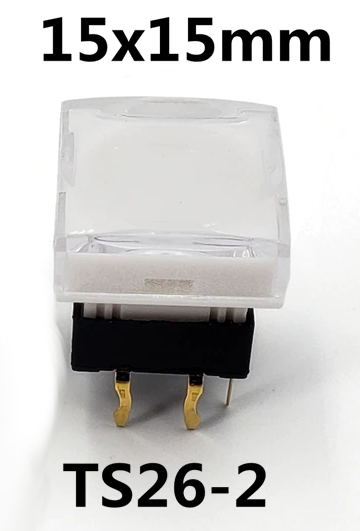
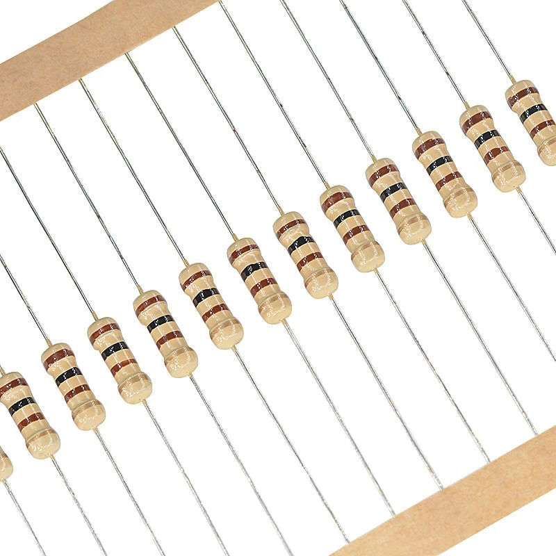
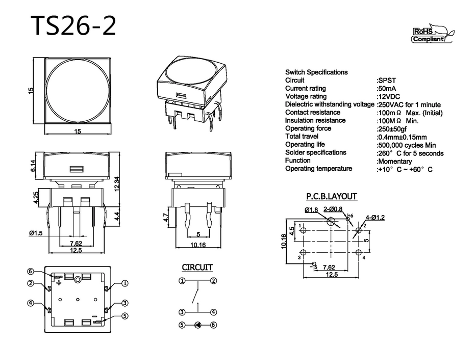
Product description of the buttons and micro controller, as found on aliexpress:
- Honyone TS26 Series Square With LED Momentary SPST PCB Mini Push Button Tact Switch –> [12x 0.81 euro, when I bought them].
- PRO MICRO/MINI/TYPE-C USB 5V 16MHz Board Module For Arduino/Leonardo ATMEGA32U4-AU/MU Controller Pro-Micro Replace Pro Mini 1PCS –> [1x 5.62 euro, when I bought it – I took the USB-C one].
Some more details on the button:
The 3D cover files (blender + stl), and symbol sheet (open office):
Key Matrix?
Why do we actually call a key-matrix a matrix? The schema I did draw at the top of this page did not really look like a matrix 😉 So here’s another attempt. The horizontal and vertical lines are the rows and columns. They do not connect to each other at the spots where they cross each other. The connections are made by the keys at each intersection:
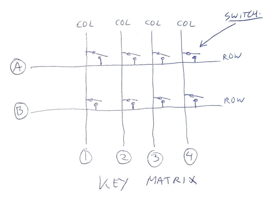
The way the micro-controller “reads” the matrix, is by changing the logic level of one of the columns, and then it measures to see if one of the rows is also changing state. If so, then the key on the intersection must have been pressed to make contact between that row and column. And this is then tried in turn for every column (and repeated at a fast pace). As mentioned before; a “real” keyboard will also use a diode on each switch intersection in series with the switch to allow flow in only one direction. This is to allow multiple keys to be pressed at the same time. In my simplified matrix setup there are key combinations which will lead to having extra phantom keys to be seen as pressed while they are not.