ESP8266 Pins To Use
Whenever you use an ESP8266 in a project, you have to choose which pin’s to use for what functions. Not all pin’s are equally suitable to use. Some have special functions, or require special handling during startup.
This website: https://randomnerdtutorials.com/esp8266-pinout-reference-gpios/ has an excellent list of pin names and functions, with a description of which ones to use or not to use.
Here is a copy of their summary table. You should visit their site if you are interested in more information, or want to see the different pin layouts for the different ESP development boards. This copy is just in case their site ever disappears 😉
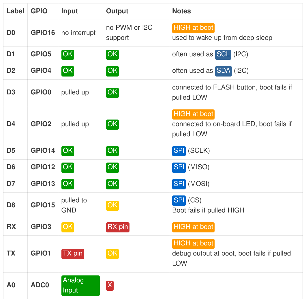
Pin input/output colours:
- GREEN: those pin’s are fine to use.
- YELLOW: you can use those, but watch out during boot up pin behaviour.
- RED: better not use those pin’s if possible.
And remember that D3+D4 have pull-up resistors, D8 has a pull-down resistor, and in many cases D4 is connected to an on-board LED. In the past I have made the mistake a couple of times to use that pin for serial data transfer, and ended up with an annoying flashing led. So nowadays I always check this pin description table.
If you want to use A0 (analog input), check the information for the used development board. The bare ESP chip supports 0-1V, and most development boards support 0-3.3V on that pin.