
WiFi 240V AC Led Dimmer – Speech Controlled
Updated March 11, 2020.
GitHub Project: https://github.com/atkaper/wifi-240v-ac-led-dimmer
TL;DR
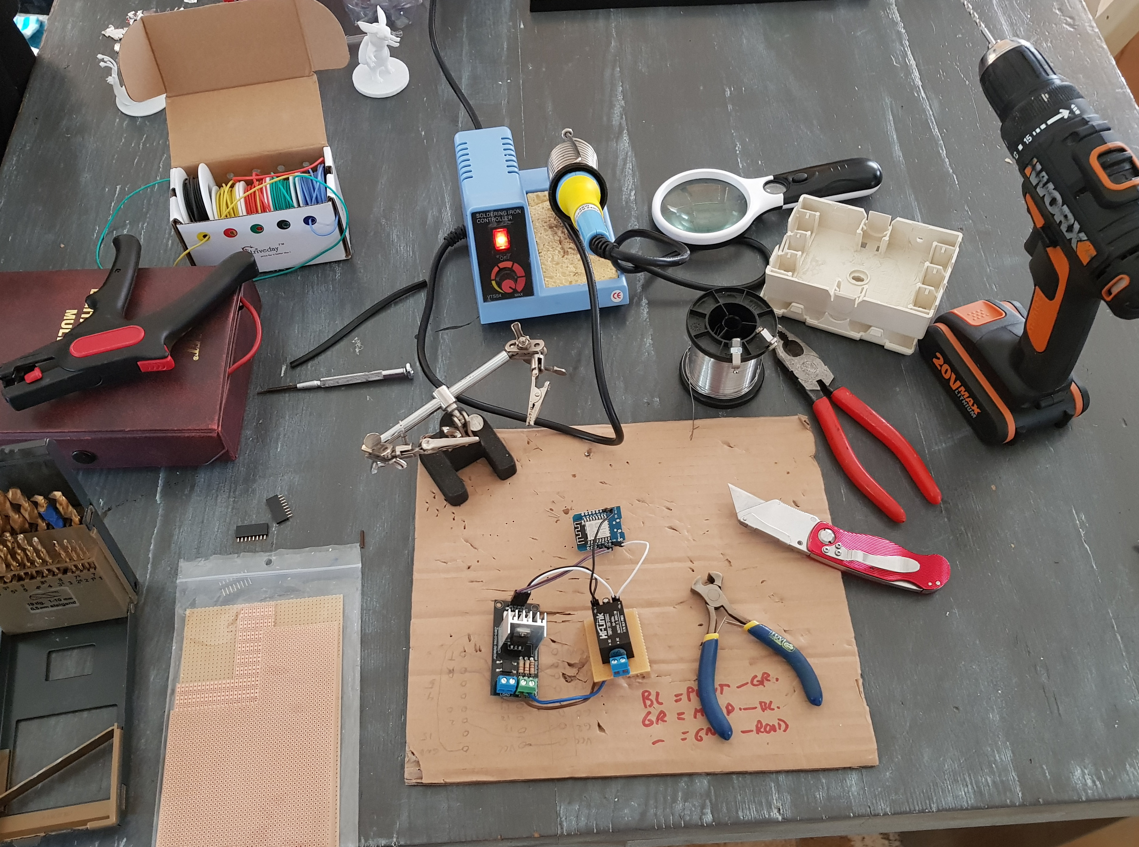
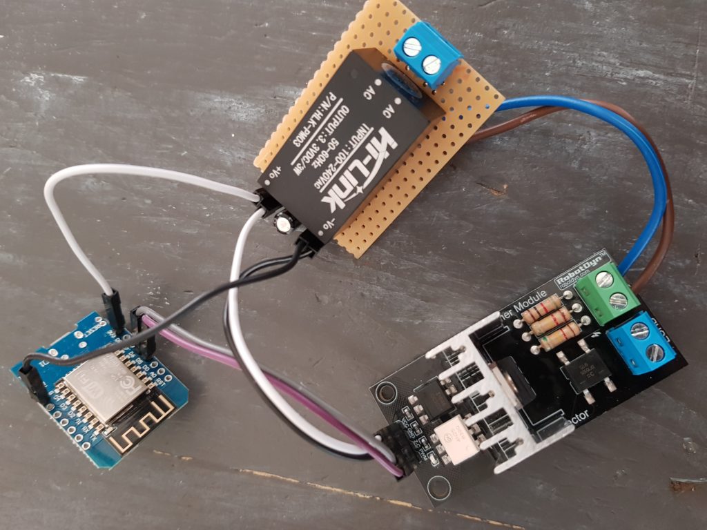
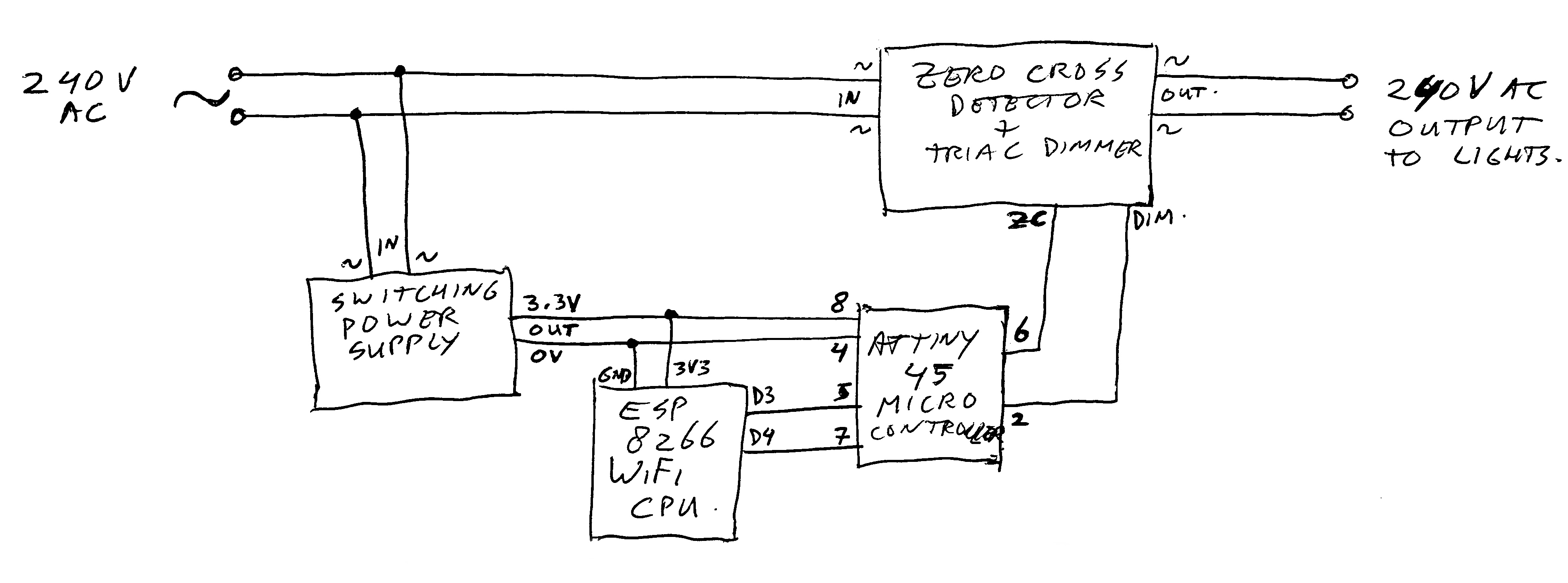
I wanted to build my own WiFi dimmer, to connect my dinner table lights to Alexa (Amazon Echo Dot). The used parts are an ESP8266 (I used a Wemos D1 Mini Clone), an ATTiny45, some sort of power module to supply 3.3 volt, and a zero-cross-detector / Triac dimmer module. The software end-result is a combination of DimmerTest_ESP_V4 with AvrDimmerCoprocessor_V3.
The Long Story
The story started with a nice offer in a cheap goods shop, of quite big (12,5 cm wide) light bulbs, with built-in WiFi control. So I bought 4 of them. Three of them I did hang above my dinner table, and #4 was the spare one.
After all wiring was done, neatly tucked away in plastic tubes, we could start to use them. And that was when “disaster” struck… For some reason, the bulbs make a high frequency noise (like an old fashioned antique tube TV). I’m old enough not to hear this anymore, but my two daughters could not stand the sound of it. Very effective teenager repellent. And the weird part was that the sound stays on, even if the lights are off (probably a cheap high frequency switching power supply). As a half measure, I did add a wireless switch, to cut the power to the lights when they were off. But using them was really a no-go. So they had to go (the lights, not the kids).
So what’s next? I did need some lights, and the wiring was done by now. The new plan was to buy similar light-bulbs, but then the ones without built-in WiFi. As there is no switch in the wiring, the next step was to “design” and build my own WiFi light dimmer.
After some googling around, I found a nice dimmer module. It has a (AC sine wave) zero-crossing detector, and a Triac (electronic switch). You can use it to dim 240V AC lights. It works on 3.3 or 5V, has a digital output for the zero-cross detection, and a digital input to “start” the Triac to conduct at a given moment until it switches off again at the next zero crossing.
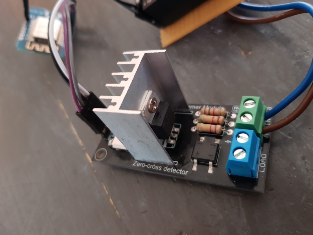
Dimmer (top) 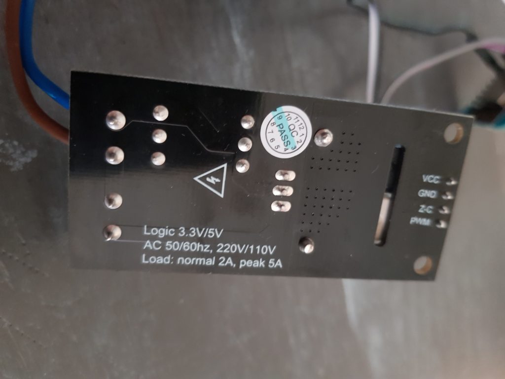
Dimmer (bottom) 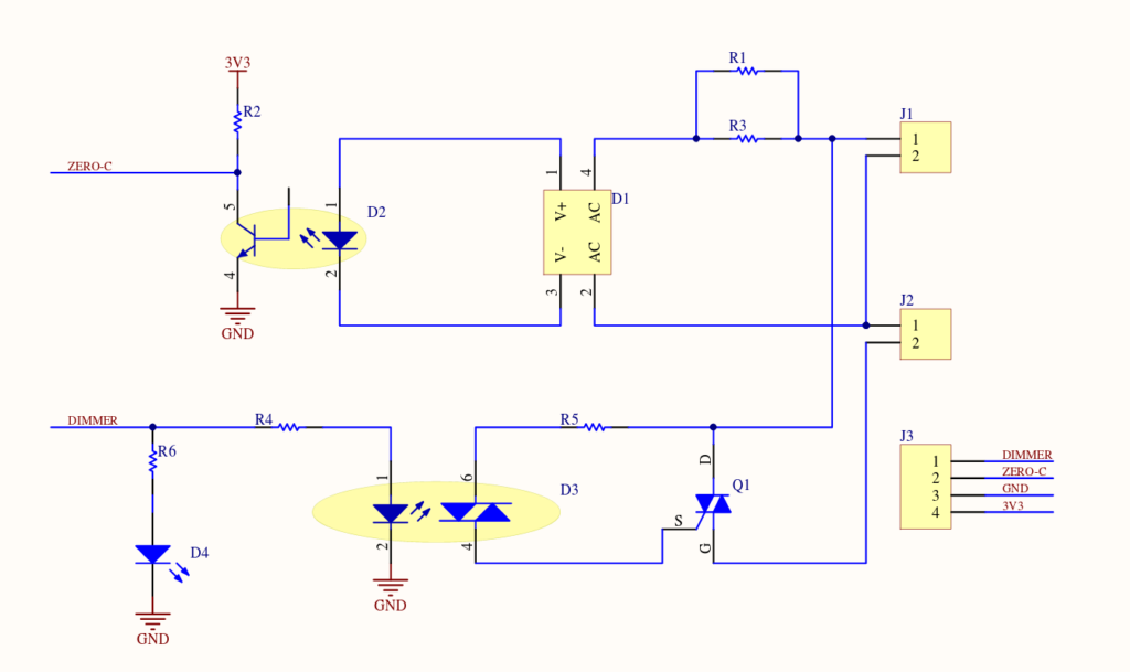
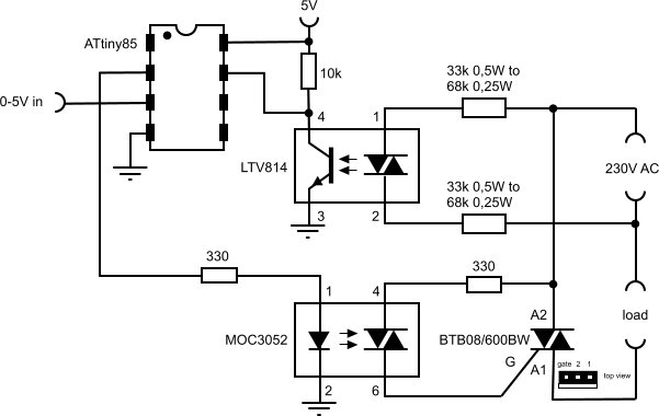
Dimmer (schematics) 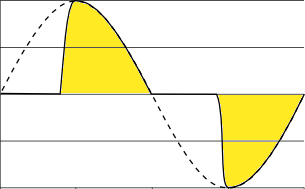
Theory of phase cut dimming
The plan was to connect this to an ESP8266 WiFi arduino-like processor. Apart from having WiFi, it has the ability to look at interrupts, and trigger the Triac after a configurable delay. Sounds perfect for the use-case!
So I did build my version 1 setup, and hacked together the program as can be found in DimmerTest_ESP_V1. It did work sort-of. I could brighten or dim the lights by pointing my web-browser to the web form which was served by the ESP module. But… the lights kept flickering like a candle in the wind. Nice as special effect, but not for regular dinner use.
Version 1 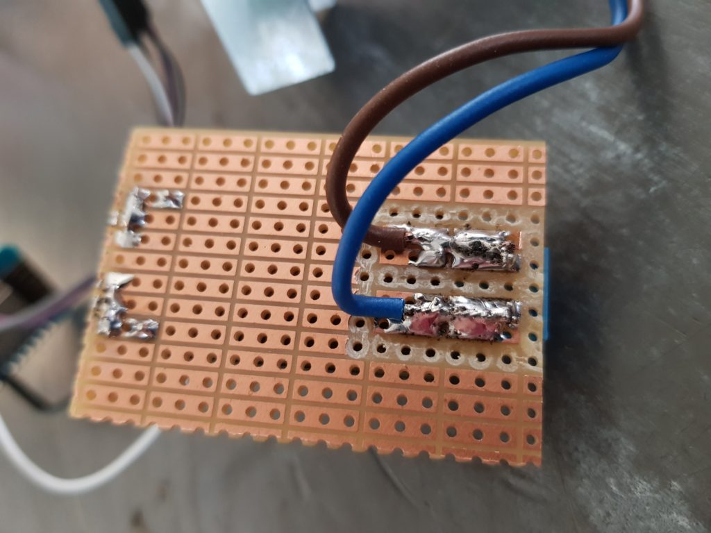
Bottom of power brick print
My guess is that the ESP has too much to handle for keeping the WiFi alive. It seems to interfere with the needed clean interrupt routines for sine phase triggering at an exact moment in time. Any shift in time has as result that the brightness changes, causing the candle flame effect. Too bad. Some more googling showed that someone else also ran into this issue.
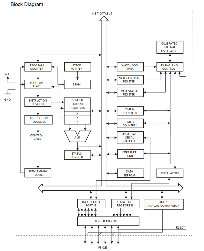
New plan; why not add a dedicated Co-Processor chip to do the actual dimming, and keep the ESP for the WiFi control functions. There is this nice little chip called an ATTiny45 (or you can use an ATTiny85), which is an 8 pin micro-controller with lots of useful building blocks inside. It has timers, interrupt handling, serial communication capabilities, and more. It is even programmable with the same Arduino Studio GUI as I do use for programming the ESP chips. Nice!
The whole setup does not even change that much. Just adding the ATTiny between the ESP and the dimmer module does the trick.
To test if the ATTiny could do phase cut dimming nicely, I used the program in AvrDimmerCoprocessor_V2A. It was a copy/paste from a forum (why re-invent the wheel), and it worked nicely using a potentiometer connected to the analog input on the ATTiny. So no WiFi control yet.
Forum Inspiration 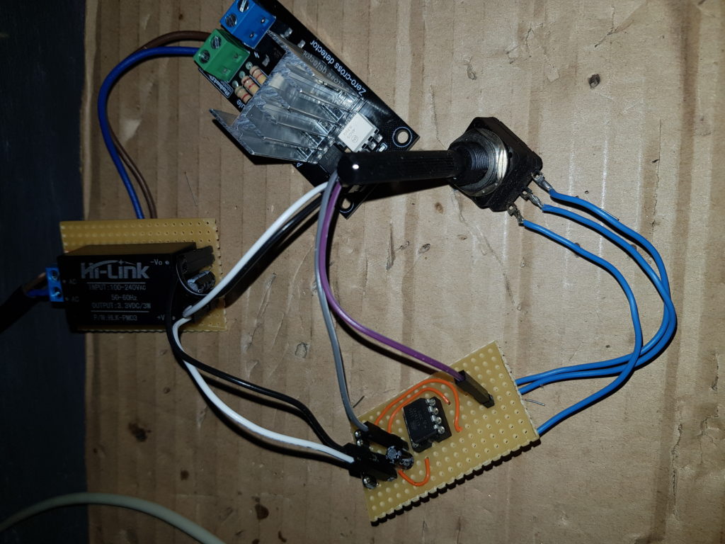
Version 2A (top) 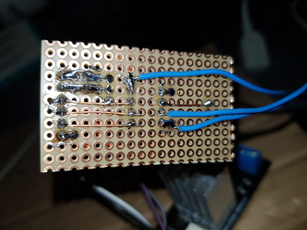
Version 2A (bottom)
Next step was modifying the code to look like AvrDimmerCoprocessor_V2B. I had to free up one of the pins as used by the original forum copy/paste example. That pin I did need after this new test for I2C serial communications. That pin has a dedicated interrupt routine connected, so to free it up, I had to use a different interrupt mechanism. The so called “pin change interrupts”. These monitor ALL data pins for which you enable it, connected to a single interrupt routine. In that routine, you need to check for which pin (if more than one enabled), and for which edge (falling or rising) the interrupt was.
Happy to see that V2B also worked nice, I could change it further to remove the analog input with the potentiometer, and change to I2C serial (digital) input. That’s in the final version piece of code as can be seen in AvrDimmerCoprocessor_V3.
Now to check if the ESP was able to talk as I2C master to the Co-Processor ATTiny slave device, I did create simple program DimmerTest_ESP_V3A. It uses the “Wire” library to talk I2C, using pins D3 (SDA), and D4 (SCL). These two pins have an on-board pull-up resistor on the Wemos D1 board, which were nice to re-use for the necessary I2C signal termination.
Apart from the Wire library, I also put in a web server, WiFi manager, and OTA-update (over the air updates). A super simple web form gave the option to change a brightness number between 0 and 100, which was send over I2C to the Co-Processor.
And again, it works! No flickering candle in the wind anymore. Smooth dimming. Fixed for a bit more than one Euro, and some nice extra hobby time.
As I did want to control the lights using voice, I looked for a library which works with Alexa (Amazon Echo Dot). The library I found was the “FauxmoESP” library. I took the standard example code, and added the I2C Wire code to it. The fauxmo stuff seems a bit outdated, so I did not manage to combine it (yet) with the WifiManager. WifiManager is a standard library with which you can dynamically configure the WiFi network (SSID+Password) to use. So for now the settings are hardcoded. Will leave that for “later”.
The end result can be found in code DimmerTest_ESP_V3B. Which talks to AvrDimmerCoprocessor_V3 in the ATTiny.
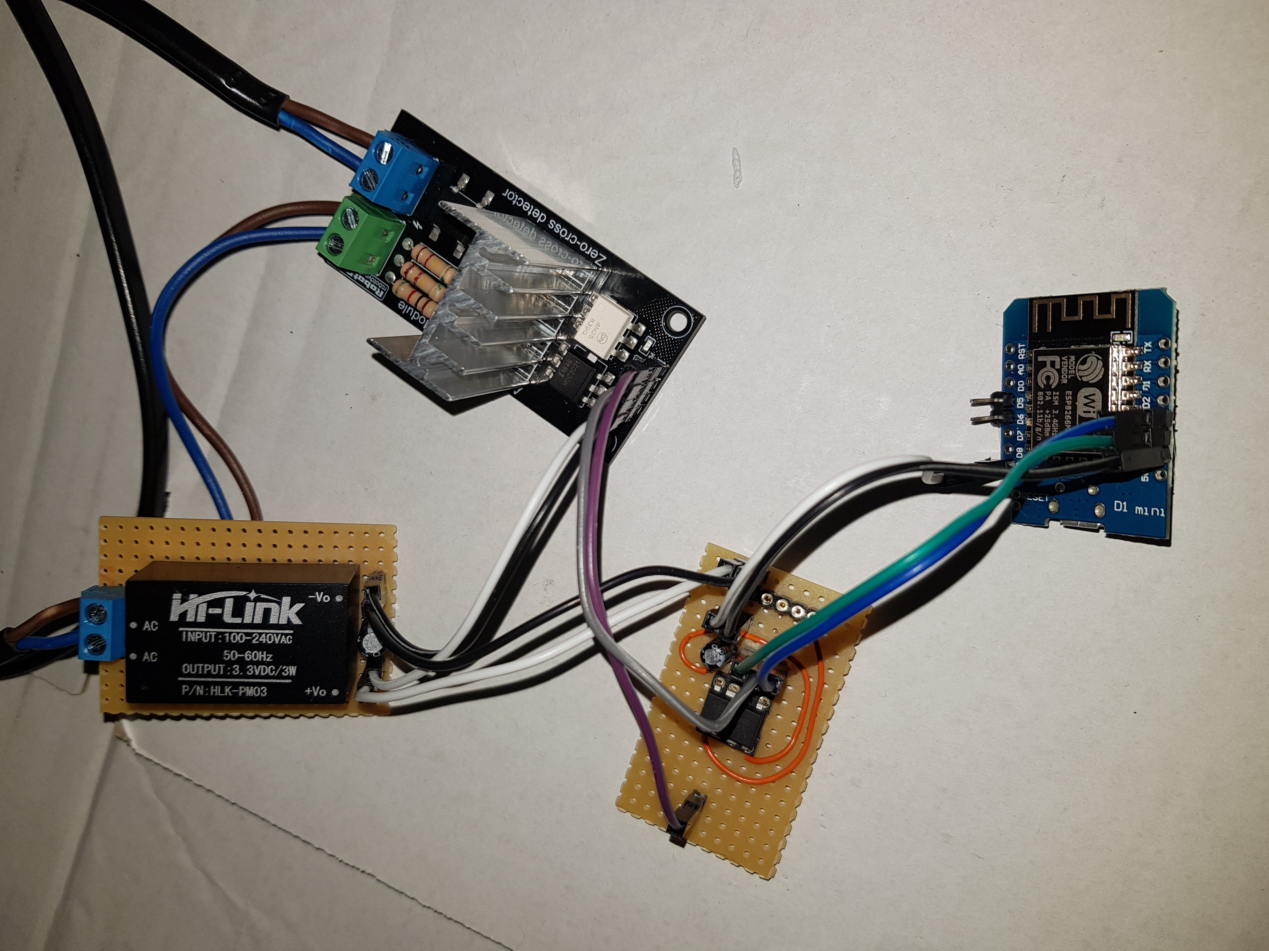
Note: for the observant photo viewing people… I did use two small electrolytic capacitors. One on the power supply board, and one on the ATTiny board. Both to get rid of any noise on the power rails.
Two things left TO-DO; put the circuit in a suitable enclosure (either a standard project box, or a 3D printed one), and I want to 3D print a minimalistic lamp cover for the light bulbs.
Thijs Kaper, 12 October 2019.
Addition:
In the last days since building this, we did experience the occasional lightning like flashes when the lights should be off. As an attempt to overcome this, I did modify the Co-Processor code to start at “off” on reset, and to make sure when brightness is set to zero, that it will not trigger the triac in any way. Also added a pull-up resistor of 10K between pin 1 and 8 (reset and vcc) of the ATTiny. This to make sure that no noise from the air does trigger a reset.
Let’s see if this helps… If not, then I will change the I2C data flow. I’m thinking of adding a fixed start byte, and repeat the brightness a couple of times. Only when the start byte is as expected, and the repeated brightness is the same, we should act on it.
But first… See if the other changes fix the issue.
Thijs Kaper, 25 October 2019.
Another addition:
I tried creating a V4 of the Coprocessor code, which has an interrupt back-off mechanism to try to block false trigger pulses. Apart from this, the V4 was refactored to use a second comparator for the pulse width, higher width resolution, and some other small changes.
But too bad, this one did function worse than the V3. The V3 still has an occasional flickering, but V4 had lots more flickering.
So I will have to go back to the drawing board, create a V5 which has a phase locked loop to sync exactly with 50 Hz (or just stay at V3, it’s not that annoying).
Thijs Kaper, 8 December 2019.
And the March 2020 addition:
My Alexa stopped working with the dimmer. Not sure what caused it, perhaps an update in Alexa code? If found a new libray, called Espalexa. It had more recent updates than the FauxmoESP one. I installed the library in my Arduine IDE, and generated the EspalexaBasic example. To this example I added my I2C code, and OTA update option, and installed it on the ESP. Works fine again now. See DimmerTest_ESP_V4 for the end results.
Thijs Kaper, 11 March 2020.
Appendix
Used AVR Programmer
To program an ATTiny, you need a separate programmer. The ESP8266 in Wemos D1 Mini form has its own on-board USB connector for programming. Both can be done via Arduino IDE. Tip: to program the ATTiny fuses (fuses are functionality switches), choose to write the bootloader. It does not actually add a bootloader, but sets the fuses. In my case I needed to set it to run on 8 MHZ with internal oscillator to get the proper timing. The 5 pin cable connector together with the separate blue VCC wire fits in the 6 pin header I placed on the ATTiny board.
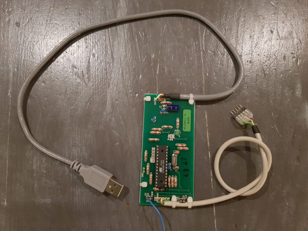
AvrUsb-500 (top) 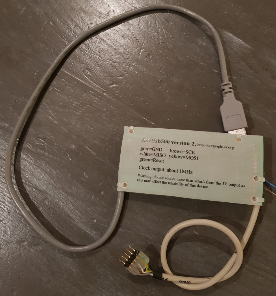
AvrUsb-500 (bottom)
Software Links
Here are some links relevant for this article. This will not be complete, but you’ll find any missing stuff (and the “how to’s”) on the web.
- https://www.arduino.cc/en/Main/software – Arduino IDE, used both for ESP and ATTiny
- In Arduino IDE, add board manager URL’s for using ESP and ATTiny (in file -> preferences): http://arduino.esp8266.com/stable/package_esp8266com_index.json,http://drazzy.com/package_drazzy.com_index.json – Install both ESP8266 and ATTinyCore via Tools -> Board -> Manager.
- https://github.com/SpenceKonde/ATTinyCore – ATTiny Core for Arduino IDE – sources / README’s.
- Obsolete – use (7) – https://bitbucket.org/xoseperez/fauxmoesp/src/master/ – The Alexa Connector Library
- https://github.com/me-no-dev/ESPAsyncTCP – needed for fauxmo
- https://github.com/me-no-dev/ESPAsyncWebServer – needed for fauxmo
- https://github.com/Aircoookie/Espalexa – The new library to use together with Alexa
Note: most other needed libraries can be installed from the Arduino IDE using Sketch -> Include Library -> Manage.
Search terms for used products (on AliExpress, or eBay)
- “AC Light lamp dimming LED lamp and motor Dimmer Module, 1 Channel, 3.3V/5V logic, AC 50/60hz, 220V/110V” – (approximately EUR 3,22 for 1) – brand: “RobotDyn”, it has a zero-crossing detector and Triac on board.
- “10pcs D1 mini – Mini NodeMcu 4M bytes Lua WIFI Internet of Things development board based ESP8266 WeMos” – (approximately EUR 19,17 per 10).
- “2pcs/lot HLK-PM03 AC-DC 220V to 3.3V Step Down Buck Power Supply Module Intelligent Household Switch Converter” – (approximately EUR 4,37 per 2) – brand: “Hi-Link”.
- “10PCS ATTINY85-20PU DIP-8 ATTINY85 DIP8 85-20PU ATTINY85-20 DIP new and original” – (approximately EUR 11,69 per 10).
2 thoughts on “WiFi 240V AC Led Dimmer – Speech Controlled”
Compliments!
a really nice job!
If you have time, could you draw a complete and more detailed scheme of how you can reproduce your work?
Thanks for the compliment. The schematic “Full Schematics of Version 3” actually shows all needed components with their pin names / numbers, and the wiring to use. The only thing missing in the image is two small capacitors (I think I used 0.1 μF electrolytic ones, but any small value will do). These remove any electrical noise on the power lines. You connect them between the Vcc (3.3V) and Ground (0v) lines. Make sure you connect them the proper way around, those electrolytes have a plus and minus side.