3D Printed Lamp Covers
My last electronics project was creating a LED dimmer for some dinner table lights. This all works fine, but the bare light bulbs were a bit bright to look at directly. The MVP (Minimal Viable Product) version to fix this problem consisted of some ugly paper strips, taped to the bulbs 😉
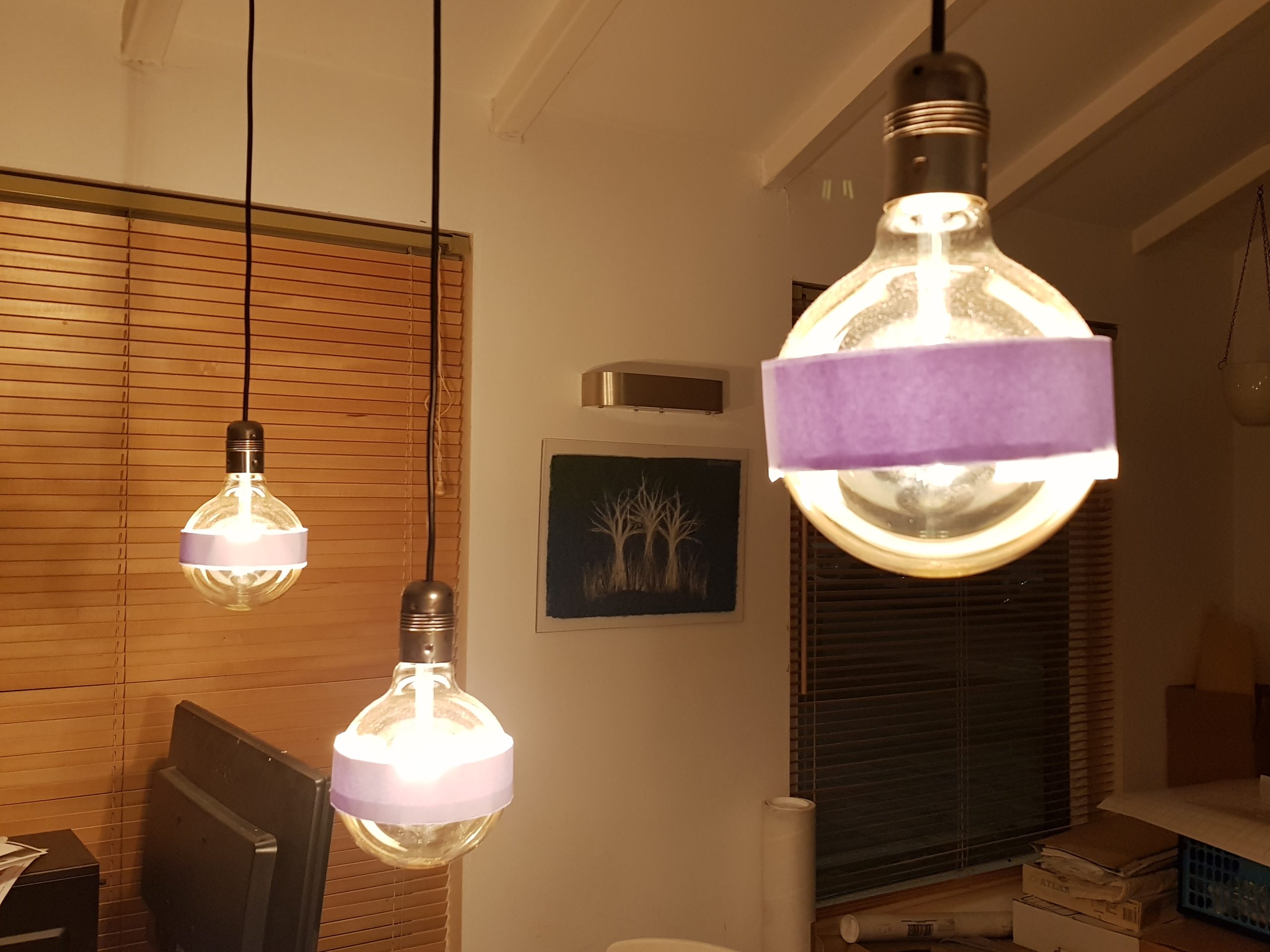
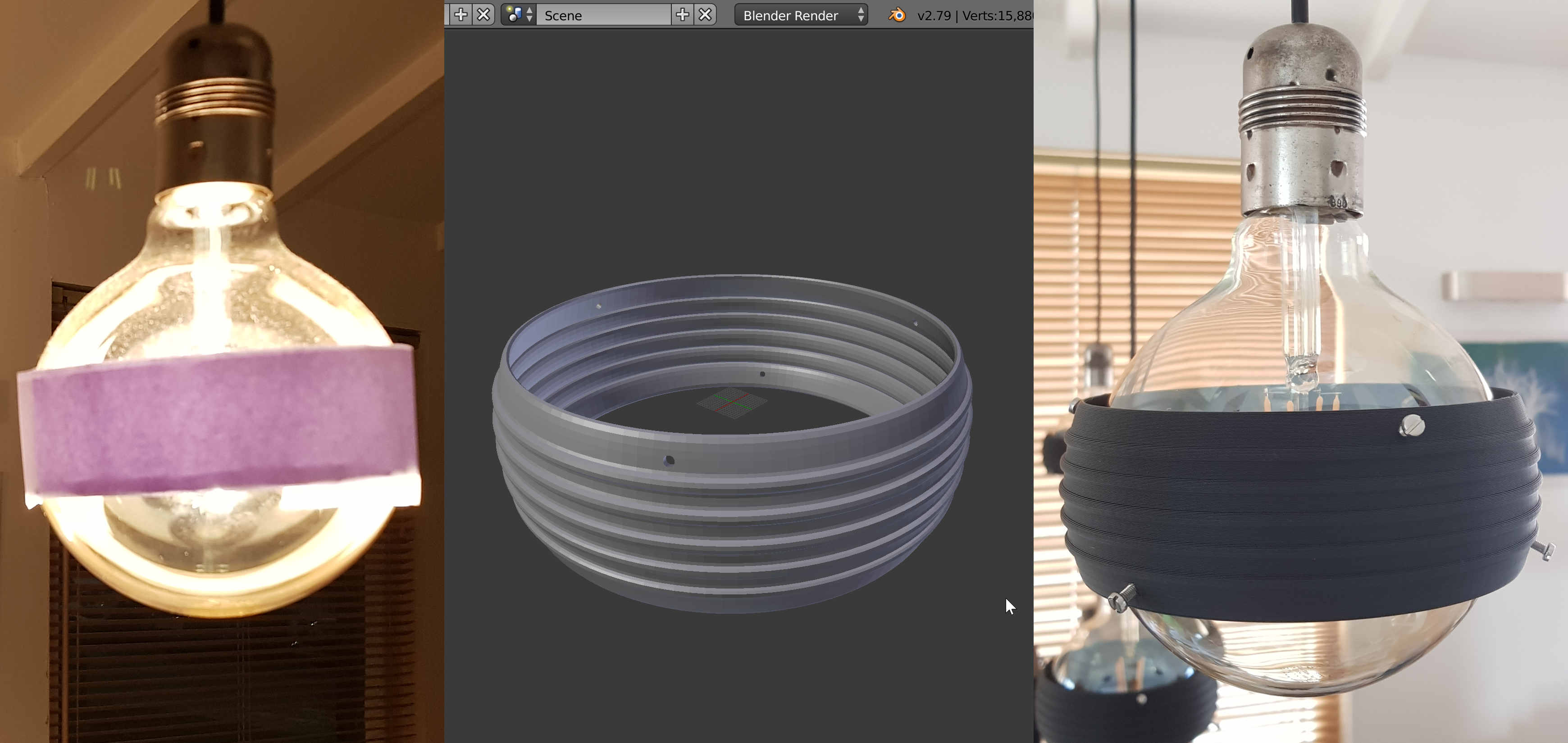
Even though this MVP version did help, it doesn’t look too good, so a long-term-solution was needed. The lamp fittings are metal, and have some ribs which make me think of the ribs on tin cans holding conserved food. This sparked the idea to make a ring shaped cover with similar ribs on it (industrial style design). Just like it would be if we cut out a part of a tin can. I actually have looked for tin can’s of the right size, but didn’t find any… So on to our own design and build.
The light bulbs are approximately 12 cm in diameter, so the plan was to create something with a 14 cm diameter around it to have some distance from the lamp.
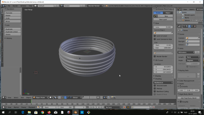
I fired up blender (the 3D modeling program), and created this:

That sounds much easier than it was. I’m not a blender-pro, and had to look up some manuals, and try some different ways of drawing this. In short; I drew a sphere, cut off the top and bottom, added ribs, smoothed the result, gave it some mass (thickness), and cut some holes.
At the end of this post, I have added the full drawing instructions, and a video of the drawing process. So if you want to reproduce something similar, you can use that as guideline.
Between designing and printing, you need to convert the design “stl” model file to print instructions in a gcode file. I did use the Cura slicer program for this.
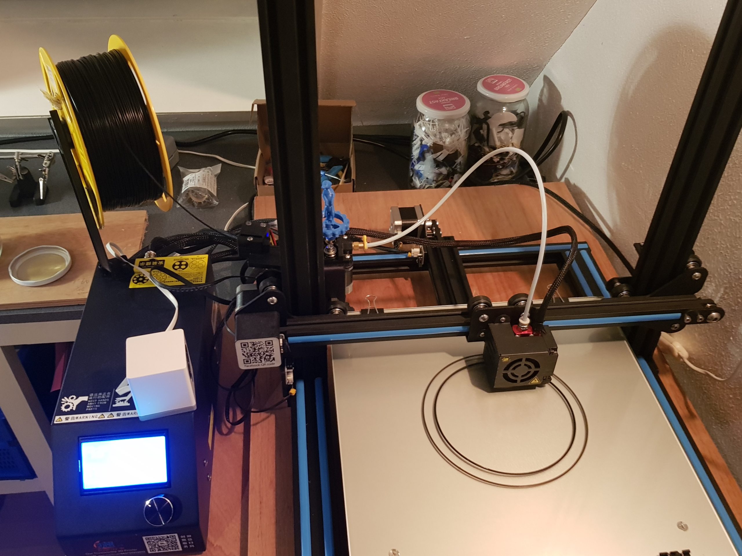
Next was firing up the 3D printer, and print the thing (using PLA plastic);
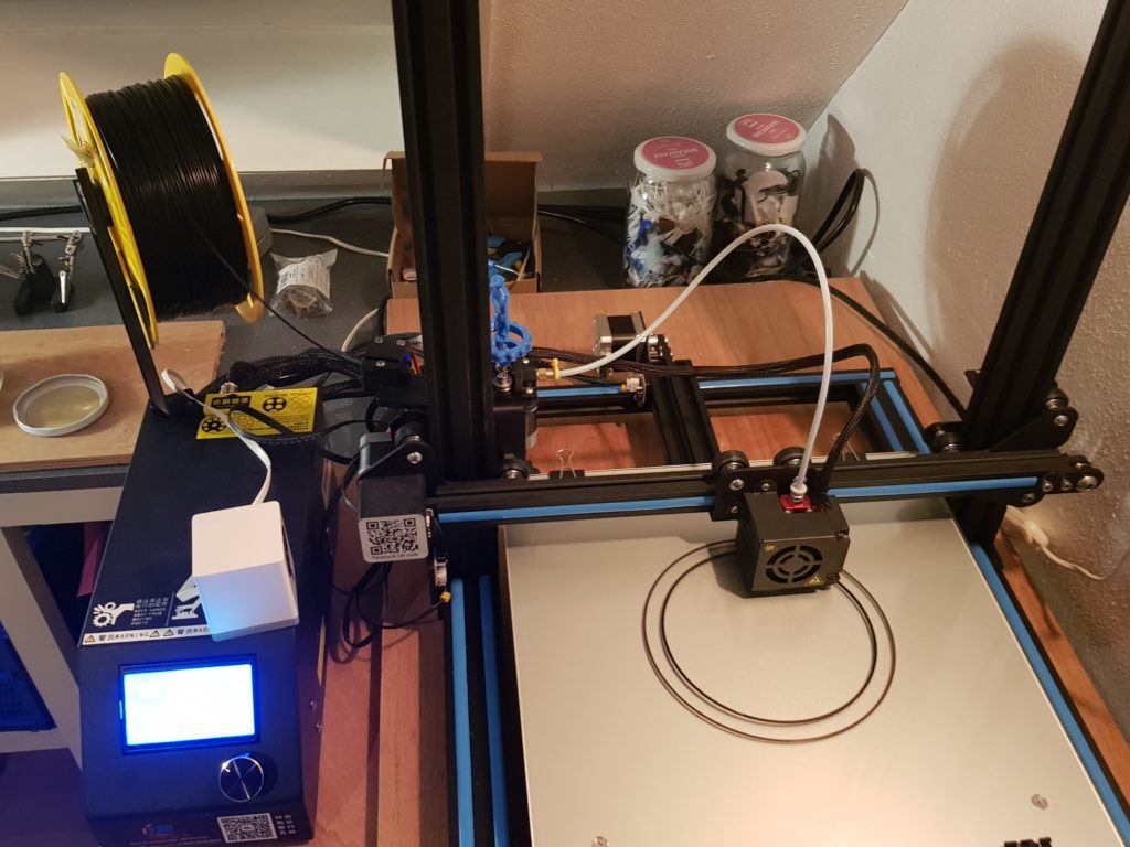
Start printing 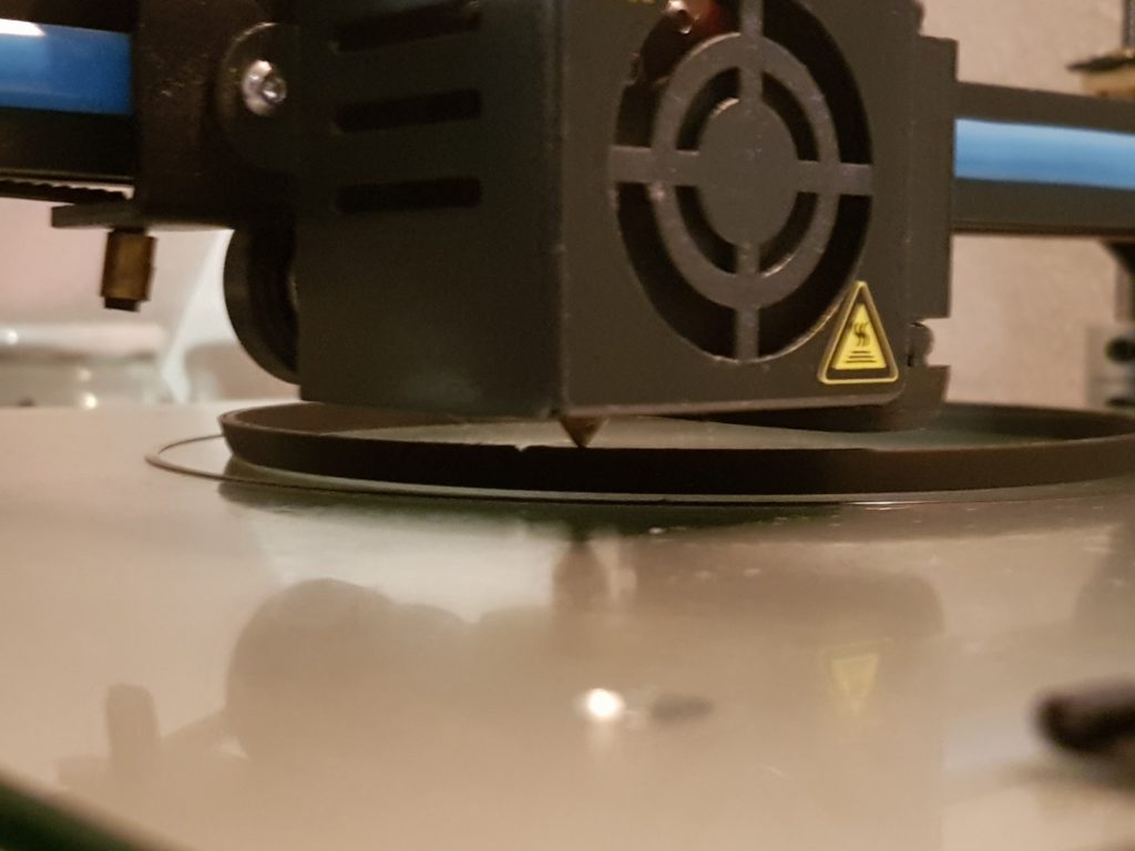
Printing around the holes

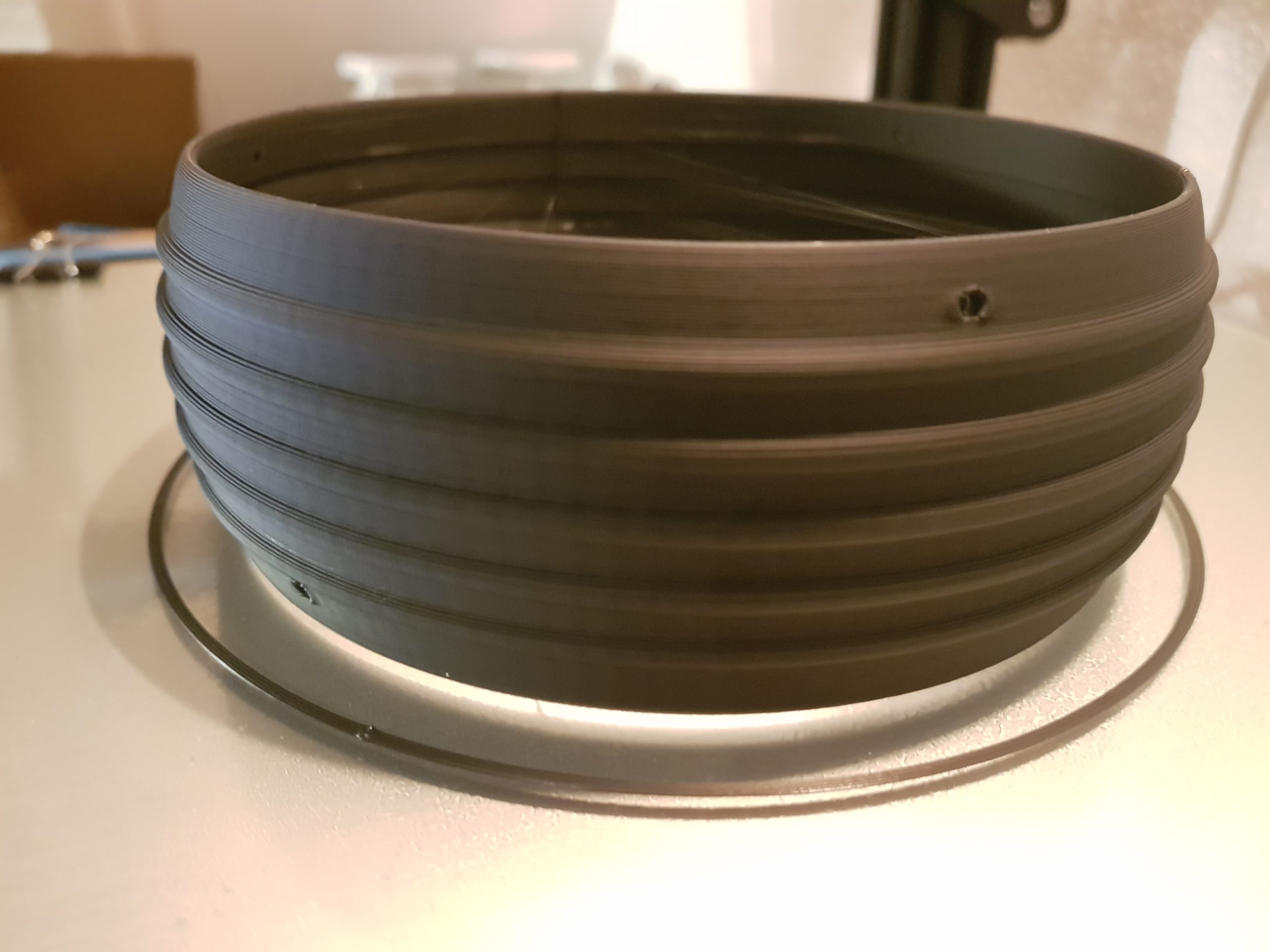
And then the final end result coming off the printer:
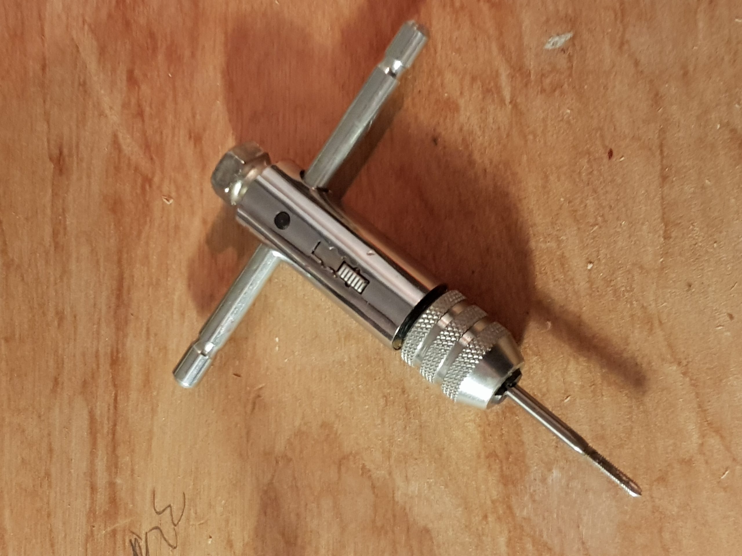
After the prints were ready, I made threads in the holes, using a thread tapping tool;
And then the final result… Note: we do plan on painting these covers silver, with possibly some black shining through (dry brushing), to match the lamp fittings. For now they are black, and work quite well.
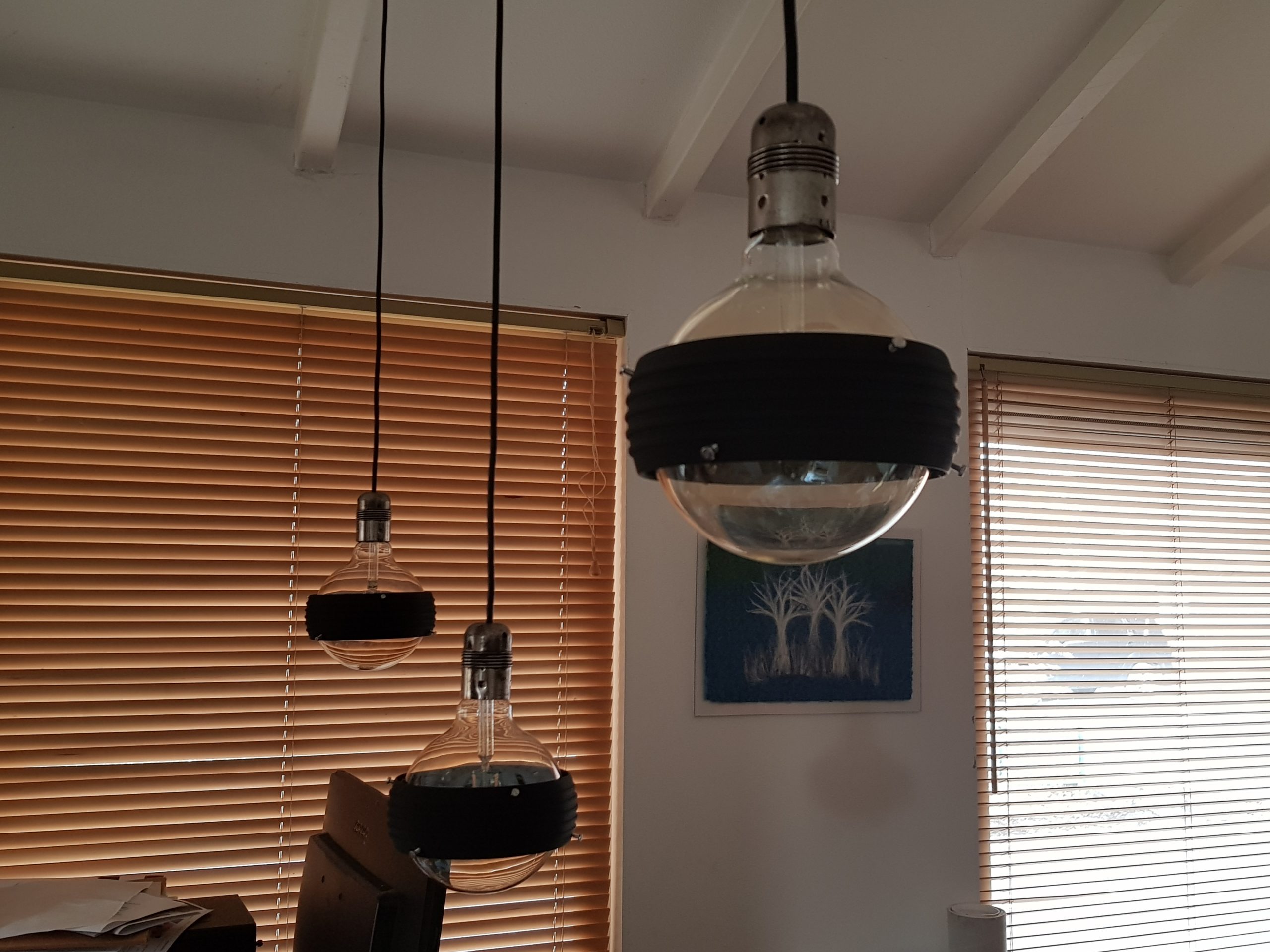
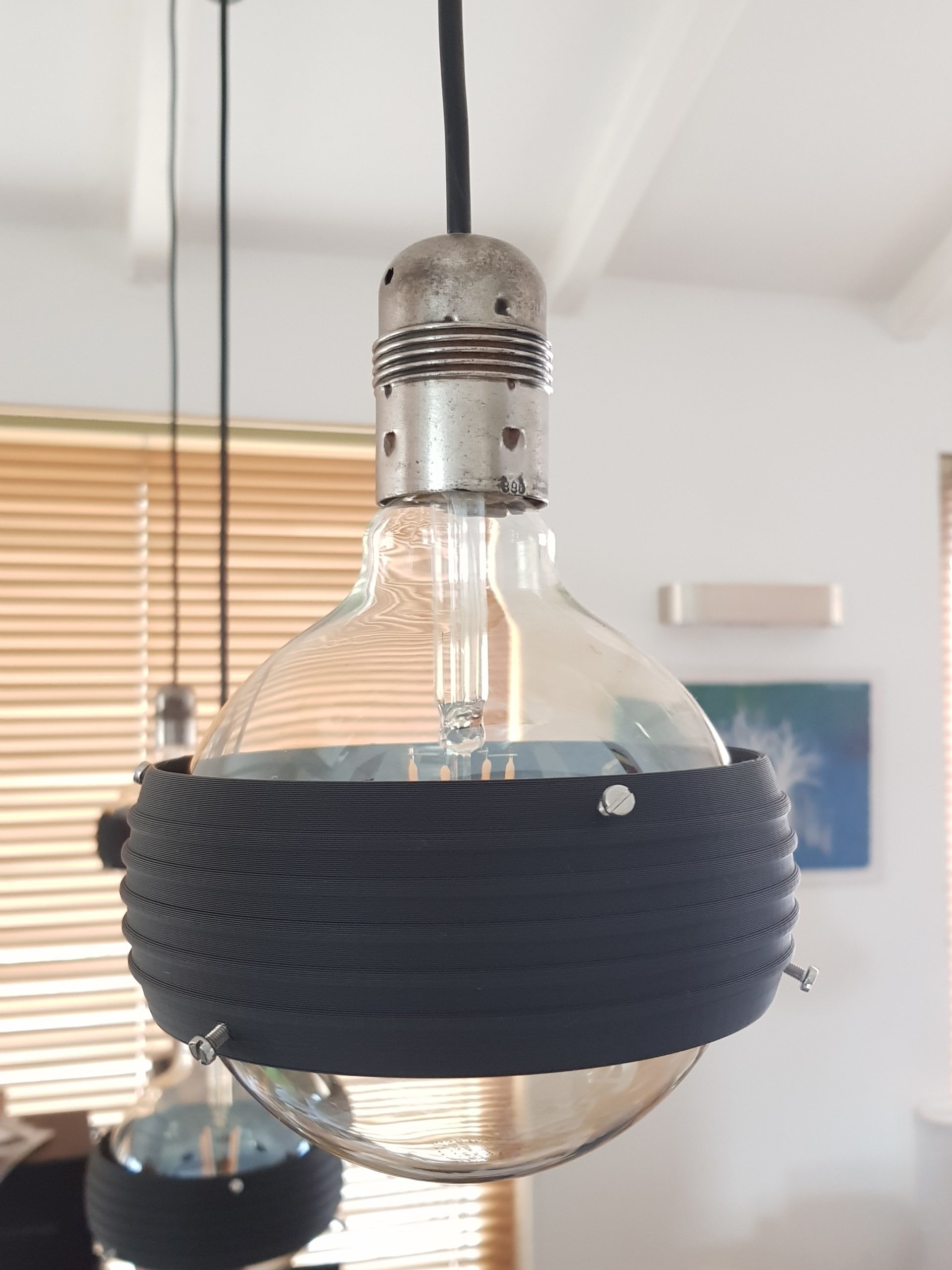
Note: the light bulbs stay really cold, because they are led lamps. No danger of heating up or melting anything… And I did make sure the bolts were not tightened too much, as that would break the glass.
That’s it. If/when we paint the covers, I’ll update this page to add a new photo… 😉
Thijs Kaper, 19 January 2020.
Appendix: Design Video and Steps
For people who are curious what it looks like to draw in 3D (no audio);
- start blender (I used 2.79b, the newer version has a different layout, so I will need to re-learn where the tools are hidden).
- general tips: mouse scroll-wheel = zoom in/out, mouse hold middle button + move = look around / rotate view, RIGHT button = select.
- make workspace empty (remove objects by right clicking, and hitting x + enter).
- set space properties -> units = millimeters.
- optional: change display grid. I used 20 lines, with 10mm distance.
- optional: set 3D cursor to 0,0,0 if you accidentally moved it, like I did.
- add mesh “uv sphere” -> segments 100, rings 32, size half of desired diameter in mm (for my example 70 to get a 14cm ring).
- in transform properties menu (at left, if invisible hit n), set x,y,z location to 0 (scale should all be 1, dimensions the desired diameter).
- add mesh “cube” -> radius same as sphere in mm (example 70).
- in transform menu, set x,y = 0,0 and z = previous diameter + half of desired ring height (example 70 + 25 = 95).
- select sphere by right clicking it.
- go to modifiers menu (wrench symbol) -> add modifier -> boolean -> operation “difference” -> Object select cube -> hit apply.
- select kube by right clicking it.
- change z location to negative number, same value as it was positive (example -95).
- now you should see that the top of the sphere is decapitated.
- select the sphere (or what’s left of it).
- go to modifiers menu -> add modifier -> boolean -> operation “difference” -> Object select cube -> hit apply.
- select kube by right clicking it.
- delete kube by hitting x.
- now you should see that the bottom of the sphere is gone also, it’s now a solid ring shape.
- select the sphere, and hit TAB to go from object mode to edit mode (wire frame view).
- in the bottom toolbar, choose “face select”.
- right click the top of the ring, and hit x and choose “delete faces” to delete the top cover.
- right click the bottom of the ring, and hit x and choose “delete faces” to delete the bottom cover.
- now we have a hollow (see through) ring.
- in the bottom toolbar, choose “edge select”.
- hold ALT+SHIFT, and right click the middle 5 lines which loop around the ring (hit the horizontal lines, not the vertical ones).
- DON’T move the mouse during the next 3 steps! (when I accidentally did, I got weird results – ctrl-z is your friend in that case).
- hit ctrl+b and type 1.5 and ENTER, this creates extra lines around the selected ones (1.5 above and 1.5 below).
- hit e and ENTER, this extrudes (zero sized), or in other words makes a “copy” of the newly added lines.
- hit s, and type 1.015 to scale out the copied extra lines. They now look like sharp edged rings (you can play with / vary the 1.015).
- hit TAB to switch to object mode (nice rendered view, no longer the wire view).
- go to modifiers menu -> add modifier -> “subdivision surface” -> view/render = 1 (or 2 for more smoothness) -> hit apply (this makes the edges smooth / rounded).
- this almost looks like the finished object, but it has no real thickness, so this can not be printed.
- go to modifiers menu -> add modifier -> “solidify” -> thickness (T) = 2 -> hit apply (now the ring wall is 2 mm thick).
- almost there… now let’s drill some small holes, which we can later change into 3mm (M3) screw thread using a thread tap tool after printing.
- add mesh “cylinder” -> vertices 100, radius 1.25, depth 200.
- in transform menu, set x,y,z location to 0, and set X rotation to approximately 73. change it in a way that the created “stick” sticks through the upper part of the ring, around the middle of the flat part. we will use it to pinch holes in the ring.
- select the ring by right clicking it.
- go to modifiers menu -> add modifier -> boolean -> operation “difference” -> Object select cylinder -> hit apply.
- select the stick (cylinder) by right clicking it.
- in transform menu, change the z rotation from 0 to 120.
- select the ring by right clicking it.
- go to modifiers menu -> add modifier -> boolean -> operation “difference” -> Object select cylinder -> hit apply.
- select the stick (cylinder) by right clicking it.
- in transform menu, change the z rotation from 120 to 240.
- select the ring by right clicking it.
- go to modifiers menu -> add modifier -> boolean -> operation “difference” -> Object select cylinder -> hit apply.
- select the stick (cylinder) by right clicking it.
- hit x to delete the stick.
- now I noticed that the top and bottom edge are not flat. It prints easier when flat, so repeat the steps using the cube to chop off a tiny bit from top and bottom. I used the cube of 70 mm, with z shifts of 93 and -93, and the boolean difference modifier to cut of a bit.
- use file -> “save as” to save the model.
- use file -> export -> “stl” to export the 3D print STL file for the model .
Note: the above zip file was made quite a while ago, I might have used slightly different ways of smoothing or different values for the design, than shown in the video and instructions.
One thought on “3D Printed Lamp Covers”
This is great! Despite seeing bulb attachments like this out in the wild, I couldn’t find anything online.
My idea is to attach two half-cones around the bulb to deflect light at the ceiling and at the table below. The inside will be painted silver to reflect light.
I suppose I’ll be learning Blender now. Thanks for the write-up and the inspiration.